


- 25 -
Hardware Installation
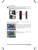
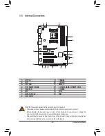
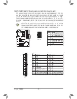
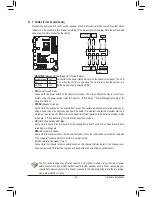
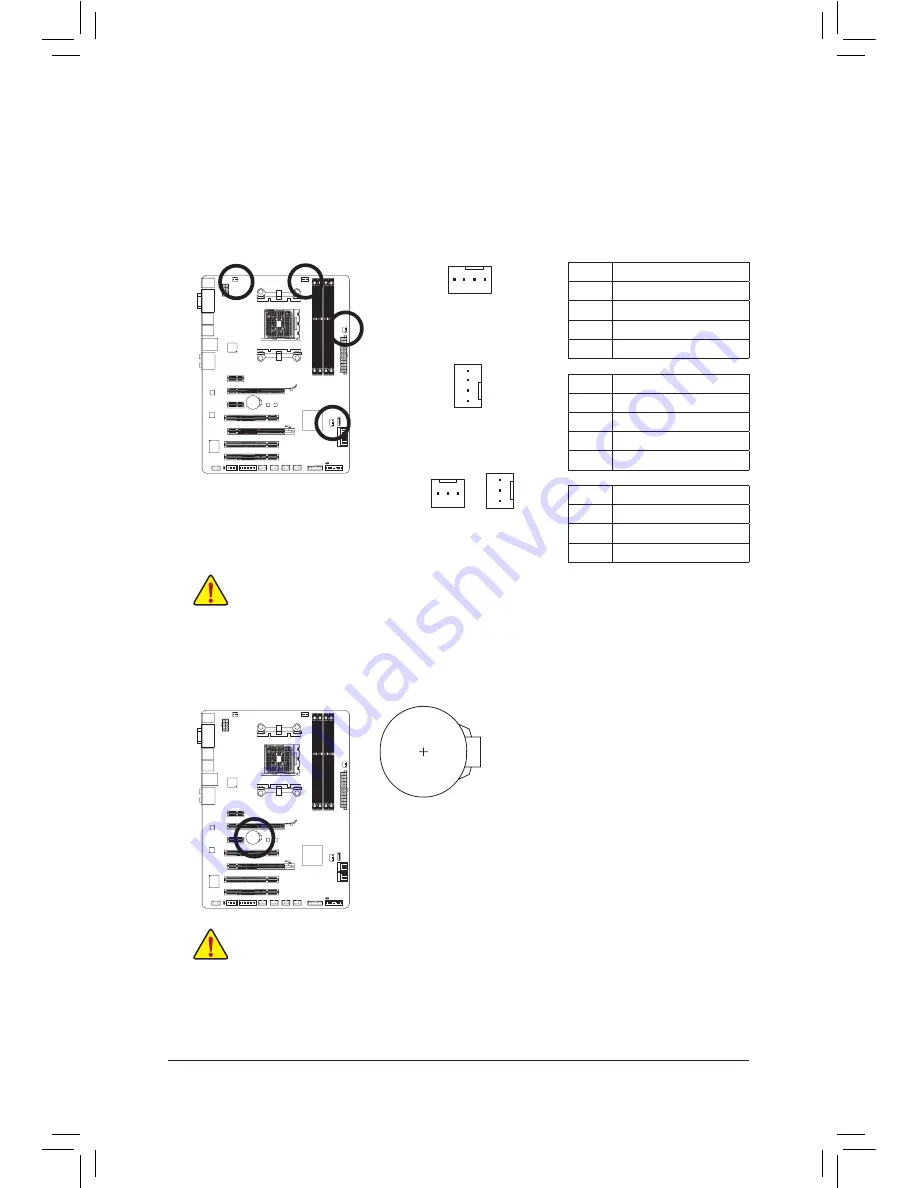
3/4/5) CPU_FAN/SYS_FAN/SYS_FAN2/PWR_FAN (Fan Headers)
The motherboard has a 4-pin CPU fan header (CPU_FAN), a 4-pin (SYS_FAN) and a 3-pin (SYS_FAN2)
system fan headers, and a 3-pin power fan header (PWR_FAN). Most fan headers possess a foolproof
insertion design. When connecting a fan cable, be sure to connect it in the correct orientation (the black
connector wire is the ground wire). The motherboard supports APU fan speed control, which requires the
use of a APU fan with fan speed control design. For optimum heat dissipation, it is recommended that a
system fan be installed inside the chassis.
Be sure to connect fan cables to the fan headers to prevent your APU and system from overheating. Over-
•
heating may result in damage to the APU or the system may hang.
These fan headers are not configuration jumper blocks. Do not place a jumper cap on the headers.
•
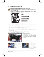
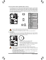
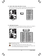
You may clear the CMOS values by removing the battery:
1. Turn off your computer and unplug the power cord.
2. Gently remove the battery from the battery holder and wait for one minute.
(Or use a metal object like a screwdriver to touch the positive and negative
terminals of the battery holder, making them short for 5 seconds.)
3. Replace the battery.
4. Plug in the power cord and restart your computer.
•
Always turn off your computer and unplug the power cord before replacing the battery.
•
Replace the battery with an equivalent one. Danger of explosion if the battery is replaced with
an incorrect model.
•
Contact the place of purchase or local dealer if you are not able to replace the battery by your-
self or uncertain about the battery model.
•
When installing the battery, note the orientation of the positive side (+) and the negative side (-)
of the battery (the positive side should face up).
•
Used batteries must be handled in accordance with local environmental regulations.
6) BAT (Battery)
The battery provides power to keep the values (such as BIOS configurations, date, and time information)
in the CMOS when the computer is turned off. Replace the battery when the battery voltage drops to a
low level, or the CMOS values may not be accurate or may be lost.
CPU_FAN
SYS_FAN
SYS_FAN2
DEBUG
PORT
G.QBOFM
DEBUG
PORT
G.QBOFM
1
1
1
PWR_FAN
CPU_FAN:
SYS_FAN:
SYS_FAN2/PWR_FAN:
Pin No.
Definition
1
GND
2
+12V /Speed Control
3
Sense
4
Speed Control
Pin No.
Definition
1
GND
2
+12V /Speed Control
3
Sense
4
Reserve
Pin No.
Definition
1
GND
2
+12V
3
Sense
Summary of Contents for GA-A75-D3H
Page 1: ...GA A75 D3H User s Manual Rev 1002 12ME A75D3H 1002R ...
Page 2: ...Motherboard GA A75 D3H Jun 13 2011 Jun 13 2011 Motherboard GA A75 D3H ...
Page 54: ...BIOS Setup 54 ...
Page 70: ...Unique Features 70 ...
Page 92: ...Appendix 92 ...
Page 93: ... 93 Appendix ...
Page 94: ...Appendix 94 ...


