


- 29 -
System Hardware Installation
3-6 Installing the CPU
Read the following guidelines before you begin to install the CPU:
• • Make sure that the motherboard supports the CPU.
• • Always turn off the computer and unplug the power cord from the power outlet before installing
the CPU to prevent hardware damage.
• • Unplug all cables from the power outlets.
• • Disconnect all telecommunication cables from their ports.
• • Place the system unit on a flat and stable surface.
• • Open the system according to the instructions.
•
WARNING!
Failure to properly turn off the server before you start installing components may cause seri-
ous damage. Do not attempt the procedures described in the following sections unless you
are a qualified service technician.
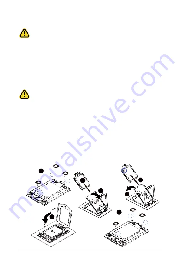
Follow these instructions to install the CPU:
1. Loosen the three captive screws in sequential order (1
g
2
g
3) securing the CPU cover.
2. Flip open the CPU cover.
3. Remove the CPU cap with CPU from the CPU frame using the handle on the CPU cap.
4. Using the handle on the CPU cap insert the new CPU cap with CPU installed into the CPU frame.
NOTE
: Ensure the CPU is installed in the CPU cap in the correct orientation, with the gold triangle
on the CPU aligned to the top left corner of the CPU cap.
5. Flip the CPU frame with CPU installed into place in the CPU socket.
6. Flip the CPU cover into place over the CPU socket.
7. Tighten the CPU cover screws in sequential order (1
g
2
g
3) to secure the CPU cover in place.
3
1
2
1
External cap
2
3
CPU
4
5
6
1
3
2
7
• • To tighten the CPU cover screws, use T20-Lobe driver to tighten 3 captive nuts in sequence as
1-3.
• • The screw tightening torque: 16.1 ± 1.2 kgf-cm (14.0± 1.0 lbf-in)
Summary of Contents for G262-ZO0
Page 1: ...G262 ZO0 HPC Server 2U DP AMD OAM 4 GPU Server User Manual Rev 1 0 ...
Page 10: ... 10 This page intentionally left blank ...
Page 16: ...Hardware Installation 16 1 3 System Block Diagram ...
Page 46: ...System Hardware Installation 46 GPU 54V Power Cable GPU Riser Power Cable Bo om Board ...
Page 48: ...System Hardware Installation 48 HDD Back Panel Board NVMe Signal Cable ...
Page 49: ... 49 System Hardware Installation PCIe Signal Cable ...
Page 50: ...System Hardware Installation 50 System Power Cable Power Supply Signal Cable ...
Page 58: ...BIOS Setup 58 When Boot Mode Select is set to Legacy in the Boot Boot Mode Select section ...
Page 63: ... 53 BIOS Setup 5 2 4 1 Serial Port 1 Configuration ...
Page 71: ... 53 BIOS Setup 5 2 8 PCI Subsystem Settings ...
Page 82: ...BIOS Setup 82 5 2 17 Intel R I350 Gigabit Network Connection ...
Page 88: ...BIOS Setup 88 5 3 1 CPU Common Options ...
Page 101: ... 53 BIOS Setup 5 3 3 1 1 Enforce POR ...
Page 147: ... 53 BIOS Setup This page intentionally left blank ...


