


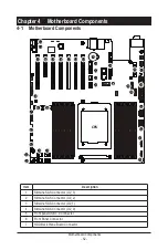
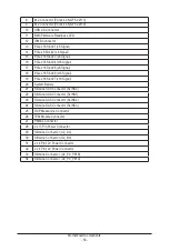
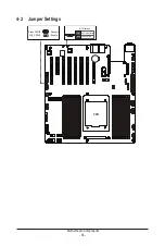


Motherboard Components
- 53 -
8
M.2 Connector (PCIe4 x4, NGFF-22110)
9
M.2 Connector (PCIe4 x4, NGFF-22110)
10
USB 2.0 Connector
11
BMC Firmware Readiness LED
12
IPMB Connector
13
PCIe x16 Slot #1 (x8 Signal)
14
PCIe x8 Slot #2 (x8 Signal)
15
PCIe x16 Slot #3 (x8 Signal)
16
PCIe x16 Slot #4 (x16 Signal)
17
PCIe x16 Slot #5 (x8 Signal)
18
PCIe x16 Slot #6 (x16 Signal)
19
PCIe x16 Slot #7 (x16 Signal)
20
System Battery
21
SlimLine SAS Connector (SLINK0)
22
SlimLine SAS Connector (SLINK1)
23
SlimLine SAS Connector (SLINK2)
24
SlimLine SAS Connector (SLINK3)
25
OCP Mezzanine Connector
26
TPM Module Connector
27
PMBus Connector
28
2 x 13 Pin Power Connector
29
SlimLine Connector (U2_A0)
30
SlimLine Connector (U2_B0)
31
2 x 4 Pin 12V Power Connector
32
2 x 4 Pin 12V Power Connector
33
SlimLine Connector (U2_P0_PE1B)
34
SlimLine Connector (U2_P0_PE1A)
Summary of Contents for G242-P35
Page 26: ... 26 System Hardware Installation 4 2 3 1 6 ...
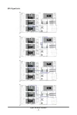
Page 43: ... 43 System Hardware Installation NVMe Card Cable GPU2 GPU0 GPU1 GPU3 GPU2 GPU0 GPU1 GPU3 ...
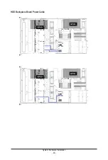
Page 46: ...System Hardware Installation 46 HDD Backplane Board Power Cable GPU1 GPU0 GPU1 GPU0 ...
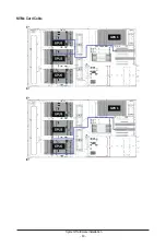
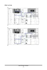
Page 48: ...System Hardware Installation 48 GPU Riser Card Power Cable GPU1 GPU0 GPU1 GPU0 ...
Page 49: ...System Hardware Installation 49 GPU Signal Cable GPU1 GPU0 GPU1 GPU0 ...
Page 51: ...System Hardware Installation 51 NVMe Card Cable GPU1 GPU0 GPU1 GPU0 ...
Page 55: ...Motherboard Components 55 This page intentionally left blank ...
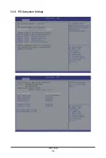
Page 66: ... 66 BIOS Setup 5 2 6 PCI Subsystem Settings ...
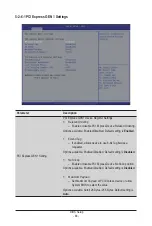
Page 70: ... 70 BIOS Setup 5 2 6 2 PCI Express GEN 2 Settings ...
Page 80: ... 80 BIOS Setup 5 2 14 Intel R I350 Gigabit Network Connection ...