


System Appearance
- 19 -
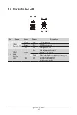
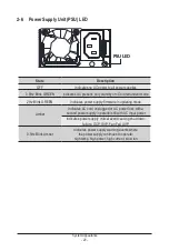
2-5 Rear System LAN LEDs
No.
Name
Color
Status
Description
1.
1GbE
Speed LED
Yellow
On
1 Gbps data rate
Green
On
100 Mbps data rate
N/A
Off
10 Mbps data rate
2.
1GbE
Link/
Activity
LED
Green
On
Link between system and
network or no access
Blink
Data transmission or receiving is occurring
N/A
Off
No data transmission or
receiving is occurring
1
2
1
2
1
2
Summary of Contents for G242-P35
Page 26: ... 26 System Hardware Installation 4 2 3 1 6 ...
Page 43: ... 43 System Hardware Installation NVMe Card Cable GPU2 GPU0 GPU1 GPU3 GPU2 GPU0 GPU1 GPU3 ...
Page 46: ...System Hardware Installation 46 HDD Backplane Board Power Cable GPU1 GPU0 GPU1 GPU0 ...
Page 48: ...System Hardware Installation 48 GPU Riser Card Power Cable GPU1 GPU0 GPU1 GPU0 ...
Page 49: ...System Hardware Installation 49 GPU Signal Cable GPU1 GPU0 GPU1 GPU0 ...
Page 51: ...System Hardware Installation 51 NVMe Card Cable GPU1 GPU0 GPU1 GPU0 ...
Page 55: ...Motherboard Components 55 This page intentionally left blank ...
Page 66: ... 66 BIOS Setup 5 2 6 PCI Subsystem Settings ...
Page 70: ... 70 BIOS Setup 5 2 6 2 PCI Express GEN 2 Settings ...
Page 80: ... 80 BIOS Setup 5 2 14 Intel R I350 Gigabit Network Connection ...