- 35 -
Hardware Installation
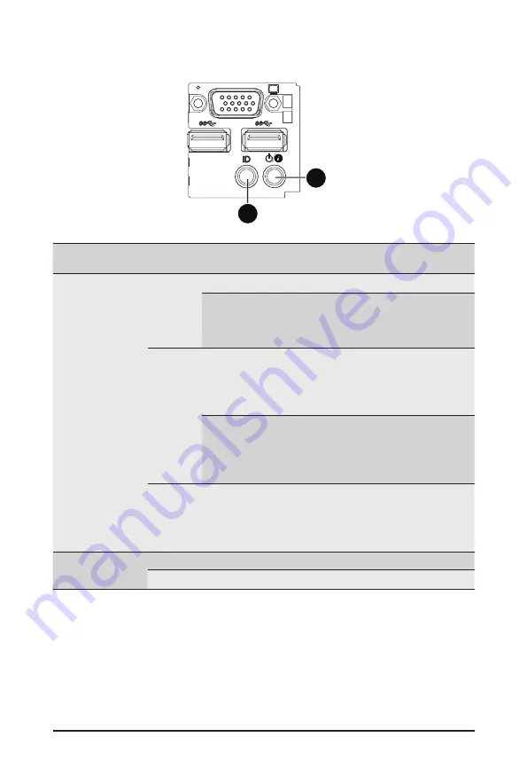
3-4 Front Panel LED and Buttons
No.
Name
Color
Status Critical
Event
Description
1.
Power
button and
Status LED
Green
Solid On
N/A
System is operating normally.
Blink
N/A
Degrade condition, may
indicates the following:
•
CPU failure
•
DIMM killed
Amber
Solid On
Yes
Critical condition, may indicates the following:
•
Power module failure
•
System fan failure
•
Power supply voltage issue
•
System temperature/voltage issue
Blink
N/A
Non-critical condition, may
indicates the following:
•
Redundant power module failure
•
Temperature and voltage issue
•
Chassis intrusion
N/A
Off
N/A
System is not ready.
May indicate the following:
•
POST error
•
NMI error
•
Processor or terminator missing
2.
ID button
and LED
Blue
On
N/A
Unit selected for identification.
N/A
Off
N/A
No identification.
1
2
Summary of Contents for H270-F4G
Page 14: ...Hardware Installation 14 1 3 System Block Diagram 1 3 1 H270 F4G ...
Page 15: ...Hardware Installation 15 1 3 2 H270 H70 ...
Page 23: ...Hardware Installation 23 CPU0 CPU1 P N 25ST1 443206 C1R P N 25ST1 443205 T4R ...
Page 34: ...Hardware Installation 34 3 3 HDD and Nodes Connection 4 2 1 3 ...
Page 52: ...BIOS Setup 52 5 2 1 Serial Port Console Redirection ...
Page 53: ... 53 BIOS Setup ...
Page 67: ... 67 BIOS Setup 5 9 SIO Configuration ...
Page 72: ...BIOS Setup 72 5 3 1 Processor Configuration ...
Page 75: ... 75 BIOS Setup 5 3 1 1 Pre Socket Configuration ...
Page 82: ...BIOS Setup 82 5 3 4 QPI Configuration ...
Page 85: ... 85 BIOS Setup Memory RAS Configuration Press Enter for configuration of advanced items ...
Page 86: ...BIOS Setup 86 5 3 5 1 Memory Topology ...
Page 95: ... 95 BIOS Setup 5 3 7 2 PCH SATA Configuration ...
Page 117: ... 117 BIOS Setup Hard Drive BBS Priorities Press Enter to configure the boot priority ...


