

34
DPT280
UK
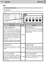
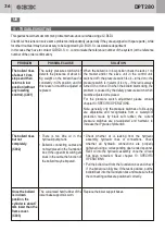
Adjustment/replacement of the
safety pressure switch. (B005)
Maximum rising pressure
adjustment. (B006)
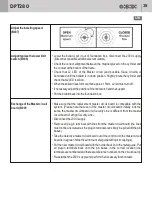
Adjust the lowering speed.
(B007)
• Position the gasket and secure the new pressure switch.
• Reconnect the pressure switch cable in the passive box.
• Restore the 230VAC power supply.
• When the bollard is in down position, check the oil level in the hydraulic unit and
top up with the same type of oil if necessary.
• When the bollard is in up position and the hydraulic unit is still (end of the rising
cycle), close the black filler cap on the hydraulic unit.
• Perform checks A010 and A011 to test correct operation.
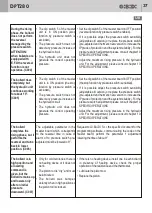
ATTENTION – before proceding check that the hydraulic unit is cold
(not
after having performed several consecutive movements which cause oil heating
inside the hydraulic system).
When the bollard is in down position, connect the pressure gauge to the pressure
outlet.
Move the bollard to up position, then check that the pressure is included in a
range
between 35 and 45 bar
.
If the pressure is inferior than the values above indicated, adjust the maximum
rising pressure.
• Lower the bollard to down position.
• At the bottom of the hydraulic unit, immediately by the side of the hydraulic
connection, there is an adjusting screw - to increase the pressure turn it
clockwise in steps of 45 ° and after each step, command a rising movement.
Once the bollard is completely up, check the pressure on the pressure gauge
and, most important, hear that the hydarulic unit continues running for about 4”
from the moment when tho bollard reaches up position (if the pressure set is
too high, the motor of the hydraulic pump may block and fail) .
• In some cases, even if after the adjustment of the maximum pressure, the
system does not reach the requested values; in this case it is necessary to
replace the hydraulic pump and send it to GI.BI.DI S.r.l. for the repair.
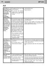
This procedure is used to synchronize installation of several bollards.
We suggest not to change the value but to maintain a speed of 2s.
• Lower the bollard, lift it out of foundation box then turn the 230V supply off.
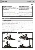
• At the top of the hydraulic unit there is a speed regulator. Loosen the tightening
nut by means of a size 19 socket wrench.
• Adjust the speed by means of an Allen screw size 4.
• To adjust the speed turn the regulator in steps of 5° (max. range 90°) by means
of a Allen key size 5.
• Once the system is synchronized, fasten the nut on the regulator by means of a
socket wrench size 19.
CONTINUES NEXT PAGE


