18
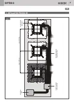
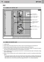
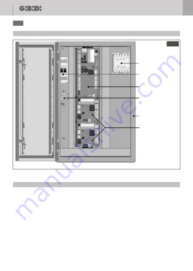
6.5 - EXAMPLE OF CONTROL UNIT
TRANFORMER
100VA 230V 0-24V
AUTOMATIC SWITCH
1P + N 6kA C216A
UNIPOLAR EARTHING
TERMINAL BOARD -
2
16 mm
METALLIC BOX
IP66 - mm 600 x 500 x 200
MASTER CIRCUIT
SLAVE CIRCUITS
EXAMPLE OF CONTROL UNIT FOR 3 GI.BI.DI. DPT280 BOLLARDS
1.
Lay the wall box.
2.
Pull the main electrical supply line (230 Vac) into the control. Connect the line directly to the main switch.*
3.
Pull the ground connection line into the control. Connect the line directly to the PE terminal.
4.
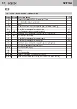
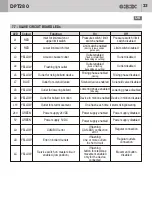
Pull the connecting cable for each bollard into the control. Connect the lines as follows: 1st bollard to the master
circuit board; each additional bollard to the corresponding slave circuit board..
5.
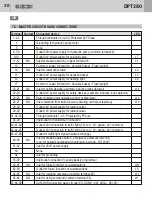
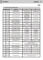
Pull the additional lines for the accessories into the control. Connect the lines to the master circuit board according
to the connection tables.
6.
Before running a functional test consult the instructions related to the electric connections provided with the
system.
* The main power supply line of the control unit must be directly connected to the main switch set inside the control
unit. Installation of the main supply line depends on the number of bollards (500W each bollard) and the distance
of the bollards to the control unit to ensure sufficient supply (230V/400V +/- 10% on the moving bollard).
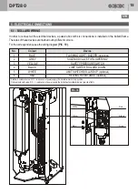
6.6 - WIRING THE CONTROL UNIT
PIC. 20
DPT280
UK

