23
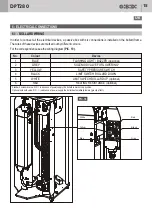
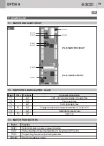
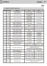
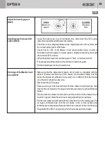
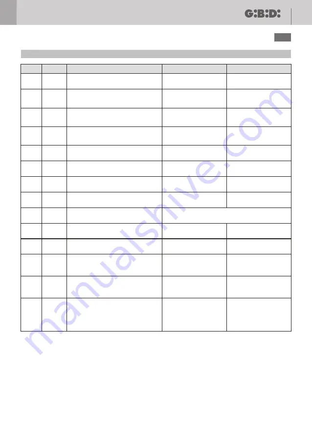
7.7 - SLAVE CIRCUIT BOARD LEDs
Colour
RED
YELLOW
YELLOW
YELLOW
YELLOW
GREEN
GREEN
RED
YELLOW
YELLOW
LED
Function
On
Off
Inlet for limit switch or
upper limit switch
CAN/BUS error
Error in bollard outlets
Service switch on master circuit
enabled (low position)
Outlet for start movement
Power supply 24VDC
Power supply 5VDC
Lower limit switch inlet
Acoustic buzzer outlet
Flashing light outlet
Pressure switch / limit
switch enabled
If flashing:
CAN-BUS connection
error
If flashing:
one or more outlets
in short circuit
If flashing:
button for step/step
movement enabled
only for the device
connected
One flash each time it starts rising/lowering
Power supply enabled
Power supply enabled
Limit switch enabled
(device in low position,
gate open)
Outlet enabled
(fixed or intermittent,
depending on setting)
Outlet enabled
(fixed or flashing,
depending on setting)
Pressure switch / limit
switch disabled
Regular connection
Regular outlets
connection
Movement button
disabled
Power supply disabled
Power supply disabled
Limit switch disabled
Outlet disabled
Outlet disabled
L1
LA
LB
LC
L16
24V
5V
L2
L3
L4
BLUE
YELLOW
YELLOW
YELLOW
Outlet for solenoid valve
Solenoid valve enabled
Rising phase enabled
(closing)
Lowering phase enabled
(opening)
Outlet for rising bollard device
Outlet for lowering bollard
Outlet for bollard in motion
Rising phase disabled
Lowering phase disabled
Device in motion disabled
Device in motion enabled
Solenoid valve disabled
L7
L6
L8
L9
DPT280
UK


