background image

27

8.3 - AUTOMATIC RISING MODE

The  minimum  configuration  of  an  automatic  high  security  bollard  with  automatic  rising  mode  consists  of  the 
following: 

One or more automatic bollards

 equipped with integrated flashing light and acoustic warning signal (define 

flashing light and acoustic warning signal depending on the system, if necessary). 

A control unit 

with radio receiver and remote control (defined the rrspective number). 

A safety inductive detector

 with 2 induction loops. 

One set of traffic lights

 (red + green) for each passage direction. 

The  bollards  are  in  the  up  position  in  normal  operation  to  block  passage.  The  integrated  flashing  lights  flash 
constantly. The traffic light illuminates red. 

The bollards lower if a corresponding command is given in order to allow passage. An acoustic warning signal 
sounds until the bollards are fully lowered (ground level). 

If the bollards are fully lowered (the position of each bollard is monitored by a sensor), the control unit switches the 
integrated flashing light off and the acoustic warning signal falls silent. The traffic light switches from red to green. The 
passage is clear 

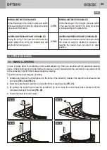
Attention: the condition AUTOMATIC BOLLARD NOT LOWERED WITH GREEN TRAFFIC LIGHT is not 
technically possible 

.

If a passing vehicle is still located above the bollards or within close proximity to them, the 2 induction loops (one 
before and one after the bollards) are active and prevent the bollards from rising. 

If a vehicle has passed through and there is no other vehicle in the immediate vicinity, the induction loops are no 
longer active. The traffic light switches from green to red. The integrated lighting strips and the acoustic warning 
signal are activated immediately after the command. The bollards start rising after approx. 4 seconds. The passage 
is blocked. 

The bollards stop and return to the lowered position (reverse command) if another vehicle is detected over the 
induction loops during rising. The point of passage can only be passed again when the traffic lights change from red 
to green. 

Following this, the bollard system reacts as previously described. 

If a pedestrian steps on a bollard during the rising phase, the safety pressure switch detects the presence of a weight 
and immediately interrupts the rising phase and makes the bollards lower to down position (inversion control by 
safety pressure switch). 

After several inversion controls, by loops or pressure switch, the situation is as described above, when bollards are in 
down position green sector turn on: instead red sector turns on when the vehicle has passed by crossing, then 
bollards start rising. If another vehicle stops over the loops, theygive a lowering control. 

After giving the corresponding command to lower the bollard, the bollard lowers and waits in this position for a vehicle 
to pass through. If a vehicle does not pass through within 30 seconds of reaching the lowered position, the bollard 
automatically returns to the up position again. 

As soon as the bollards are in the up position, the integrated flashing lights start to flash constantly, the acoustic 
warning signals fall silent and the induction loops are no longer active. The traffic light switches from green to red. The 
bollards also remain in the up position if a vehicle approaches to pass through. Passage is only enabled once a 
corresponding command is given.

DPT280

UK

Summary of Contents for DPT280

Page 1: ...DPT280 UK DPT280 Automatic bollards FITTING OPERATION AND MAINTENANCE INSTRUCTIONS ...

Page 2: ...etween contacts equal to or greater than3mmtopowerthecontrolunit The main power supply line of the control unit must be directly connected to the main switch set inside the control unit Use approved anti flame cable The dimension of the main power supply line must be evaluated by the installeraccordingtothequantityofbollards 500Weachbollard andthedistancefromtheoutputplace inorderto grantapropersu...

Page 3: ...stockedthebollardsincloseorcoveredplaces Gi Bi Di bollards are designed to resist to transport and stocking effects in a range between 25 C and 55 C and foradeterminedtime lessthan24hours at 70 C The bollards do not require any availability of spare parts Gi Bi Di S r l warehouse can send any spare parts in quicktimes In case of maintenance or repair of the bollards be sure to avoid any inappropri...

Page 4: ...rd optional automatic lowering if power failed Safety reversal pressure switch Standard Connection line to control unit Standard 10 m max lenght 80 m with heating resistance max 50 m Hydraulic pump for movement Built in into the bollard Hydraulic pump absorption 230V 10 2 2A max 3 4A Hydraulic pump thermal protection Standard intervention threshold 120 C automatic recovery 80 C Protection class IP...

Page 5: ... COMPONENTS LOWER LIMIT SWITCH LOWER SUPPORT BASE REFLECTING STRIP FLASHING LIGHT HEAD DPT280 560 560 40 150 800 275 1140 MOVING CYLINDER FRAME PASSIVE BOX PISTON HYDRAULIC PUMP SOLENOID VALVE RISING SIDEBLOCK UK ...

Page 6: ...6 5 INSTALLATION PROCEDURE 140 mm 200 mm 300 mm 1430 mm 1000 mm 1000 mm Walking level 10 mm SENSO DI TRAFFICO TRAFFIC WAY ø 50 mm PIC 1 PIC 2 PIC 3 PIC 5 PIC 4 DPT280 UK ...

Page 7: ...7 5 INSTALLATION PROCEDURE PIC 6 FOUNDATION BRACKET CONTROL UNIT JUNCTION BOX 400 x 400 mm FLEXIBLE SHEATH diameter 50 mm max 1600 mm max 1600 mm DPT280 UK ...

Page 8: ...IONAL CONCRETE CASTING SUPPORTING SLAB M8 CHEMICAL ANCHORS M16 CHEMICAL ANCHORS WATERPROOF PIT IN STAINLESS STEEL WATERPROOFING SHEATH 10 mm 50 mm 600 mm 275 mm 450 mm 500 mm 925 mm A B 700 mm 700 mm 450 mm 450 mm A dimension is the sum of the different thicknesses of which the slab is made of PIC 7 5 INSTALLATION PROCEDURE DPT280 UK ...

Page 9: ...9 PIC 8 PIC 10 PIC 11 PIC 9 M16 M16 5 INSTALLATION PROCEDURE DPT280 UK ...

Page 10: ...LATION PROCEDURE min 25 cm 5 5 cm 9 cm 15 cm 15 cm 15 cm PIC 16 PIC 15 PIC 17 Control Unit DPT280 95 cm 95 cm 95 cm 95 cm PIC 12 300 cm 70 cm max 160 cm 70 cm 90 cm 90 cm PIC 13 280 cm 200 cm 80 cm 80 cm PIC 14 UK ...

Page 11: ...te the foundation box You must provide a drainage channel with a cover grille in front of the bollard and in its immediate vicinity to prevent rainwater frompenetratingthesystem An important factor when inserting the bollard is prior assessment of the ground permeability to drain rainwater Makesurethatthegroundpermeabilityinthefittingareameetsthefollowingrequirementsinadvance Performatesttocheckth...

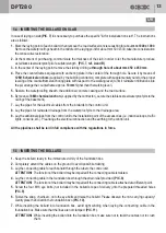
Page 12: ...hey are all turned in the same direction and precisely aligned PIC 6 6 Fillthespacearoundthefoundationboxwithgraveluptoapprox 200mmtoavoidanyobstructionofthedrainage holes placedatthebottomofthepit duringtheconcretecasting 7 Lay a flexible ø 50 mm tube from each foundation box to carry the connecting cable from the bollard to the control unit PICs2and4 WARNING If the foundation boxes and the contr...

Page 13: ...hebasement 7 Lay the pipes for the electrical cables from the bollards to the control unit 8 Lay the pipes for rainwater drainage from the waterproof pits to the drainage area 9 Lay the additional pipes from the control unit to the installation point of the accessories i e inductive loops traffic lights consolle etc Prearrangetheelectricalconnectionandtheearthingtothecontrolunit PIC 7 All the pipe...

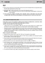
Page 14: ...teelmeshispresent removeituptoapprox 25cmabovethecircumferenceoftheinductionloop PIC 16 4 Make sure that the corners are rounded when laying the induction loop PIC 16 PIC 17 5 Lay the induction loop 7 cm beneath the ground surface In case of paving stones with a thickness of at least 10 cm the material must be adjusted to permit laying at the specified depth Alternatively you can lay the induction...

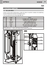
Page 15: ... 2 3 4 5 6 Colour BLUE GREY YELLOW BLACK WHITE RED Device FLASHING LIGHT BUZZER opzional SOLENOID VALVE FOR LOWERING SAFETY PRESSURE SWITCH LIMIT SWITCH BOLLARD DOWN LIMIT SWITCH BOLLARD UP optional HEATING RESISTANCE optional Standard solenoid valve N C in absence of power supply the bollard remains in up position Optional solenoid valve N O gravity effect in absence of power supply the bollard a...

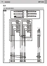
Page 16: ...e 24Vdc 1 3 2 4 2 4 2 4 4 2 1 1 2 4 2 6 BROWN 5 WHITE 3 YELLOW 1 BLUE 2 GREY Hydraulicl unit 4 BLACK M12 1 3 4 2 1 3 4 2 1 3 4 2 1 3 4 2 2 1 3 4 2 1 3 4 M11 M9 M4 M14 M6 1 13 4 15 14 16 10 x 11 2 x 9 M19 M M20 M1 M3 M13 M5 7 8 6 4 1 3 2 4 M17 M18 M10 M2 5 WHITE Sensor for detecting bollard up position 3 YELLOW Safety pressure switch 1 BLUE Flashing light and buzzer 6 RED Heating resistance 4 BLACK...

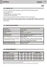
Page 17: ...6 3 CONTROL UNIT DATASHEET 6 4 HOUSING DIMENSIONS Circuit board Standard housing Protection category Supply Control unit protection Service transformer Permitted ambient temperature Relative humidity function range Max no of bollards that can be connected all bollards connected to one control always move simultaneously Controlling individual bollards is not possible with microprocessore with speci...

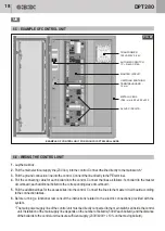
Page 18: ...control Connect the lines as follows 1st bollard to the master circuitboard eachadditionalbollardtothecorrespondingslavecircuitboard 5 Pulltheadditionallinesfortheaccessoriesintothecontrol Connectthelinestothemastercircuitboardaccording totheconnectiontables 6 Before running a functional test consult the instructions related to the electric connections provided with the system Themainpowersupplyli...

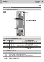
Page 19: ...tch Programming the system adjustment parameters Enter the maintenance mode Master Slave F1 F2 F3 F5 F1 F6 F7 F2 Typology Connected components 2AT 230V 24 VAC power supply unit supply fuse 1AT Timer supply fuse 2AT Traffic light supply fuse 5AT Supplytoaccessoriesconnectedtoterminals1 2 3 31 32 33 1AT 2AT Safety devices supply fuse Logic fuse F5 5AT F3 2AT PIL16 MASTER CIRCUIT PIL16 SLAVE CIRCUIT ...

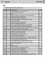
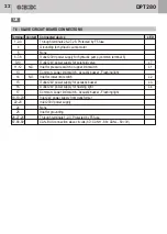
Page 20: ...tion to yearly weekly progremmer Outlet 230V power supply for hydraulic pump common terminal 8 L7 L3 L4 L1 L2 L13 L13 LIN L5 L12 L11 L14 Outlet 24V power supply for solenoid valve Outlet 24V power supply for acoustic buzzer Outlet 24V power supply for flashing light Outlet 24V power supply for radio receiver Outlet 12V power supply for radio receiver Common Lower limit switch Acoustic buzzer Flash...

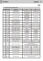
Page 21: ...Step Step Outlet for hydraulic pump power supply rising Outlet for hydraulic pump power supply lowering Outlet for hydraulic pump power supply in motion Safety devices inlet Rising phase disabled Lowering phase disabled Device in motion disabled Safety devices in alarm Safety devices free Outlet disabled red light ON Device in motion enabled One flash each time a rising lowering phase starts if pa...

Page 22: ...utlet 230V power supply for hydraulic pump common terminal 8 L7 L3 L4 L1 L2 Outlet 24V power supply for solenoid valve Outlet 24V power supply for acoustic buzzer Outlet 24V power supply for flashing light Common Lower limit switch Acoustic buzzer Flashing light Common Lower limit switch Acoustic buzzer Flashing light Inlet for pressure switch or upper limit switch Inlet for lower limit switch CAN...

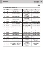
Page 23: ...sing lowering Power supply enabled Power supply enabled Limit switch enabled device in low position gate open Outlet enabled fixed or intermittent depending on setting Outlet enabled fixed or flashing depending on setting Pressure switch limit switch disabled Regular connection Regular outlets connection Movement button disabled Power supply disabled Power supply disabled Limit switch disabled Out...

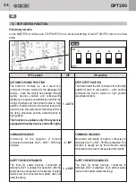
Page 24: ...EPFUNCTION The bollard after the first command from the high position moves to low position after another command the device returns to high position step stepfunction COMNANDENABLED Commands for the operation of bollard connected to terminals 24 25 26 27 58 59 are enabled SAFETYDEVICESENABLED The inlet for safety devices connected to terminals 20 21 is enabled for operation with the safety device...

Page 25: ...ocket head screw pressed until the completeloweringofthebollard PIC 26 4 Fastenthedowelremovedinstep1 RISINGLIMITSWITCHENABLED At the final stage of the rising the pressure switch worksaslimitswitchinordertocompletetherising procedureofthebollard INVERSIONPRESSURESWITCHENABLED During the rising if the pressure switch detects a weight greater than 40 Kg the bollard stops and returnstothedownpositio...

Page 26: ... inductionloopsduringrising If a pedestrian steps on a bollard during the rising phase the safety pressure switch detects the presence of a weight and immediately interrupts the rising phase and makes the bollards lower to down position inversion control by safetypressureswitch If the bollards are in the lowered position due to a reverse command they only rise again after receiving another command...

Page 27: ...ffic light switches from green to red The integrated lighting strips and the acoustic warning signal are activated immediately after the command The bollards start rising after approx 4 seconds The passage isblocked The bollards stop and return to the lowered position reverse command if another vehicle is detected over the induction loops during rising The point of passage can only be passed again...

Page 28: ... to keep the system in operation in case of temporary power failures it can be equipped with an emergency powergenerator UPSdevice The control unit can be equipped with a weekly yearly timer e g in order to regulate loading unloading times in traffic calmed areas The control logic of timers acts in the exact same way as previously described The acoustic warningsignalscanbedeactivatedatnightbyusing...

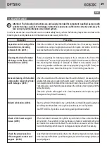
Page 29: ...ally or fully block or become calcified over time meaning that drainage of rainwater is limited or not possible at all To remove any possible calcification take an appropriately long drill Ø 15 mm and drilltheopeningsclear Lowerthedrillapprox 10cmintothegravelbelow Rise the cylinder if the bollard is dry Lubricate the central sliding guide external partofthepistonthatslidesonthecylinder andthepist...

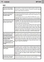
Page 30: ...witch detects a pressure increase usually caused by the detection of a weight corresponding to 40 kg or more on the bollard e g a person the bollard stops and goes back to down position Check the proper functionality of the safety reversal managed by the pressure switch using a sample weight e g a barrel filled with 40lt of water Otherwise adjust or replace the pressure switch Read chapter10 SPECI...

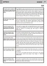
Page 31: ...owering device check that the manual lowering device works properly Read chapter 10 SPECIFIC OPERATIONS If the system is equipped with radio receiver and transmitters check the correct operation from a distance of about 30m and as far as possible verify the wear of thetransmittersandthebuilt inbatteries Check visually the overall status of the control unit and in particular verify that there are n...

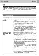
Page 32: ...aulic unit is still end of the rising cycle closethecapofthehydraulicpump Liftthebollardoutofpit lowerittodownpositionthenturnthepoweroff Unfasten the black cap of the hydraulic pump of about 2 turns to reset the internalpressureofthepump Removethecoilfromthesolenoidvalve Unfasten and remove the solenoid valve by means of a fixed wrench size 24 someoilleaksmayoccur useclothtowipeitclean Verifythat...

Page 33: ...h are connected on one side 3 black wires negative power supply of the 3 light points on the other side only one black wireisconnected thisblackwirepowersthefirstpointat 24VDC Move the black wire from the first terminal to the second or the third one to poweranotherlightpoint Test the proper operation of the multiled flashing light if the test is positive reassemble the head and complete the inter...

Page 34: ...tom of the hydraulic unit immediately by the side of the hydraulic connection there is an adjusting screw to increase the pressure turn it clockwise in steps of 45 and after each step command a rising movement Once the bollard is completely up check the pressure on the pressure gauge and most important hear that the hydarulic unit continues running for about 4 from the moment when tho bollard reac...

Page 35: ... Make sure that the replacement master circuit board is compatible with the system Please note that even if the master circuit boards initially look the same the master circuit board of a Security Line is different from the master circuitboardofaHighSecurityLine Disconnectthe230Vsupply Remove all plug in terminals with lines from the master circuit board the lines must not be unscrewed as the plug...

Page 36: ...dorreplaced For the pressure switch adjustment please consult chapter10 SPECIFICOPERATIONS Note generally only the pressure switches of old supply are adjustable and recognizable from a waterproof protection made by black soft rubber the current pressure switches are pre adjusted and hermetic to increasetheIPgradeofprotection Check whether oil is leaking from the hydraulic assembly hydraulic lines...

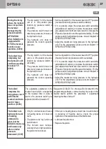
Page 37: ... belubricated The bollard was bumped violently when in high position so thepistonrodiscrooked Set the dip switch 5 of the master board in OFF position reversalfunctionbypressureswitchenabled If it is possible adjust the pressure switch sensibility adjustable old version or replace the pressure switch pre adjusted and hermetic new version to increase the IP grade of protection and the system reliab...

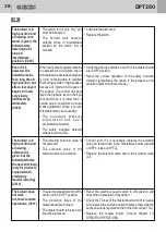
Page 38: ...is lower than a certain value it performs an auto matic adjustment When it occurs thisproblemmaybecausedby The automatic pressure a d j u s t m e n t h a s b e e n accidentallyexcluded The safety inductive detector alwaysinalarm ON Lubricatethepistonrod Replacethepiston Control and if it is necessary replace the solenoid valve protection fuse in the master slave units master unitPF4 slaveunitPF2 R...

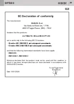
Page 39: ...the following harmonised standards have been applie Date 10 01 2020 S r l Directive LVD 2006 95 CE and subsequent amendments Directive EMC 2004 108 CE and subsequent amendments EN60335 1 EN61000 6 1 EN61000 6 3 The legal Representative Michele Prandi Moreover declares that the product must not be used until the machine in which it has been incorporated has not been declared in accordance with 2006...

Page 40: ...I DI S r l Via Abetone Brennero 177 B 46025 Poggio Rusco MN ITALY Tel 39 0386 52 20 11 Fax 39 0386 52 20 31 E mail info gibidi com Numero Verde 800 290156 w w w g i b i d i c o m Cod AIC0063 01 2020 Rev 00 ...

Reviews: