background image

User’s Manual 

GT-650                                                Software Setup                                              5-35 


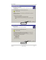
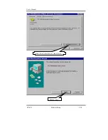
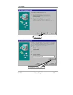
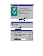
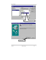
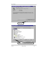
Select “Driver” then click on “Update Driver” 

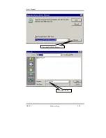
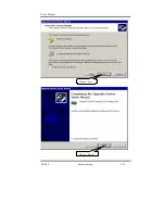
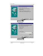
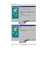
Click on “Next” 

Summary of Contents for GT-650

Page 1: ...GT 650 Pentium III Celeron w VGA LAN Audio w Video Capture GPIO Embedded Board User s Manual ...

Page 2: ...ndirect special incidental or consequential damages arising out of the use or the possibility of such damages This document contains proprietary information protected by copyright All rights are reserved No part of this manual may be reproduced by any mechanical electronic or other means in any form without prior written permission of the manufacturer Acknowledgments All trademarks and registered ...

Page 3: ...rted please check if your GT 650 package includes the following items l GT 650 Pentium III Celeron Embedded board x 1pcs l Driver Utility CD_ROM x 1 pcs l HDD cable x 1 pcs l User s manual x 1pcs l AD 011 8 ports Video input GPIO adapter card cable x 1pcs ...

Page 4: ...nced Chipset Features 4 13 4 6 Integrated Peripherals 4 16 4 7 Power Management Setup 4 20 4 8 PnP PCI Configuration setup 4 23 4 9 PC Health Status 4 25 4 10 Default Menu 4 27 4 11 Password Setting 4 28 4 12 Exit Selecting 4 29 4 13 POST Messages 4 30 4 14 POST codes 4 36 Chapter 5 Software Setup 5 1 INF update utility for 815E chipset 5 1 5 2 Intel 815E chipset Graphics control Driver 5 6 5 3 PC...

Page 5: ... operation into one compact single board computer including 2D 3D graphics accelerator 10 100 TX Ethernet adapter Two USB ports Two Ultra DMA IDE drive controllers Two high performance serial ports enhanced parallel port and the latest BIOS features Additional enhancements to the GT 688V include a sixteen channel maximum video input interface Two dual in line memory module DIMM sockets support up ...

Page 6: ...SB host interface support for four USB ports and a System Management Bus SMB with support for DIMM Serial PD 1 2 Specifications Processors Supported Socket 370 Processor Intel Tualatin Processor up to 1 4GHz FSB 66 100 133 MHz Intel Pentium III Processor up to 1GHz FSB 66 100 133 MHz Intel Celeron Processor up to 1 GHz FSB 66 100 133 MHz Memory 512MB maximum 2 x 168 pin DIMM sockets Supports PC 10...

Page 7: ...rive Floppy Ports One 26 pin slim type floppy disk interface Serial Ports One RS 232 serial ports with 16C550 compatible FIFO buffer One RS 232 RS 422 RS 485 selectable serial port with 16C550 compatible FIFO buffer Parallel Port Single parallel port controller with bi directional compatibility EPP and ECP enhanced port modes PS 2 Keyboard Mouse port Microsoft compatible Two six pin mini DIN conne...

Page 8: ...5 75 Operating Environment Temperature 0 to 55 C Humidity 5 to 90 RHNC Storage Environment Temperature 0 to 65 C Humidity 5 to 95 RHNC Current Requirements 5V typical current draw 6 10A 5V maximum current draw 8 18A 12V maximum current draw 600mA Note 1 5V current draw is processor dependent ...

Page 9: ...User s Manual GT 650 Jumper connector 2 1 Chapter 2 Jumpers and Connectors Figure 2 1 Jumper of GT 650 ...

Page 10: ...0 9 10 External speaker 14 20 HDD LED Pin8 Pin7 7 8 System reset switch 5 6 SUSLED Pin4 Pin2 2 4 PS For the AT system short pin 10 pin12 for power on Internal USB connector USB2 Signals USB2 1 USB2 2 Power 1 10 Data 3 8 Data 5 6 USB GND 7 4 CHS GND 9 2 External power connector P1 Signals P1 12V 10 5V 4 6 19 20 12V 12 5V 18 3 3V 1 2 5VSB 9 PS ON 14 POWER OK 8 Ground 3 5 7 13 15 16 17 ...

Page 11: ... Then Move JUMPER back to 1 2 OF J1 TV out mode Select JP2 Option Mode JP2 NTSC 1 2 PAL 2 3 COM2 mode Select JP3 Mode JP3 RS 232 3 5 4 6 9 11 10 12 17 18 RS 422 1 3 2 4 7 9 8 10 15 16 RS 485 1 3 2 4 7 9 8 10 13 14 CPU FSB Select JP4 Function JP4 Auto by CPU 1 3 2 4 66 MHz 3 5 4 6 FAN control FAN1 2 Function FAN1 2 Sense 3 12V 2 PWM control 1 ...

Page 12: ...at all connectors are in place and firmly attached Component Label HDD IDE connector IDE 1 IDE2 Slim FDD connector FDC Internal USB connector USB2 Reset switch connector JP1 6 5 External speaker connector JP1 14 20 HDD LED connector JP1 7 8 External power connector P1 Serial Port COM1 2 Audio OUT LINE_OUT Audio IN LINE_IN MIC MIC_IN CD IN CD_IN LAN RJ 45 Video INPUT J2 CMOS RAM clear J1 Audio GPIO...

Page 13: ... MB up to 512 MB of SDRAM Module The two 168 pin SDRAM Dual Inline Memory Module DIMM sockets will accept 64 bits DIMM modules 3 3V memory UN buffered SDRAM only The single board computer will accept only DIMM with gold plated contacts To ensure reliable operation at zero wait states use only 7 5ns or faster SDRAM DIMM for bus speeds 133MHz If more then two DIMM sockets are used they may be filled...

Page 14: ...3CT5 LGS GM71V65163CT5 LGS GM71V65163CT5 LGS GM71V65163CT5 LGS GM71V65163CT5 LGS GM71V65163CT5 LGS GM71V65163CT5 LGS GM71V65163CT5 Figure 3 2 DIMM Installation 4 Repeat Steps 1 3 for the remaining DIMM in DIMM 2 You can install two DIMMs on the board 3 2 Installing the CPU 1 Match key pin on the CPU with key pin of the PGA370 socket Please see the figure 3 3 for detail 2 To complete the installati...

Page 15: ...ower is off 2 Set the configuration jumpers in accordance with Chapter 2 Power button will be connected to pin 1 3 of JP1 3 Connect the ATX power supply to ATX connector on GT 650 4 Connect the applicable I O cables and peripherals i e floppy disk hard disk monitor keyboard power supply and etc Note the color of pin one is usually red or blue while others are gray 5 Turn on the power by power butt...

Page 16: ...mportant but non standard features such as virus and password protection as well as special support for detailed fine tuning of the chipset controlling the entire system The rest of this chapter is intended to guide you through the process of configuring your system using Setup Starting Setup The AwardBIOS is immediately activated when you first power on the computer The BIOS reads the system info...

Page 17: ...n the Setup program using the keyboard Key Function key Move to the previous item key Move to the next item key Move to the item on the left menu bar key Move to the item on the right menu bar Esc key Main Menu Quit without saving changes Sub menus Exit Current page to the next higher level menu Enter key Select the item you desired PgUp key Increase the numeric value or make changes PgDn key Decr...

Page 18: ...hat you avoid making any changes to the chipset defaults These defaults have been carefully chosen by both Award and your systems manufacturer to provide the absolute maximum performance and reliability Even a seemingly small change to the chipset setup has the potential for causing you to use the override A Final Note About Setup Not all systems have the same Setup While the basic look and functi...

Page 19: ...lts Set Supervisor Password Set User Password Save Exit Setup Exit Without Saving Esc Quit F9 Menu in BIOS Select Item F10 Save Exit Setup Time Date Hard Disk Type Figure 4 1 Main Menu Note that a brief description of each highlighted selection appears at the bottom of the screen Setup Items The main menu includes the following main setup categories Recall that some systems may not include all ent...

Page 20: ...tage control See section 4 9 for the details Load Fail Safe Defaults Use this menu to load the BIOS default values for the minimal stable performance for your system to operate See section 4 10 for the details Load Optimized Defaults Use this menu to load the BIOS default values that are factory settings for optimal performance system operations While Award has designed the custom BIOS to maximize...

Page 21: ...res Date Time IDE Primary Master IDE Primary Slave IDE Secondary Master IDE Secondary Slave Drive A Drive B Driver B Video Halt On Based Memory Extended Memory Total Memory Mon Feb 8 1999 16 19 20 2557 MB None None None None None EGA VGA No Errors 640 K 64512 K 65536 K Item Help _____________________________ Menu Level Ø Change the day month year and century Move Enter Select PU PD Value F10 Save ...

Page 22: ...s Enter to enter the sub menu of detailed options IDE Secondary Slave Options are in its sub menu described in Table 4 3 Press Enter to enter the sub menu of detailed options Drive A Drive B None 360K 5 25 in 1 2M 5 25 in 720K 3 5 in 1 44M 3 5 in 2 88M 3 5 in Select the type of floppy disk drive installed in your system Video EGA VGA CGA 40 CGA 80 MONO Select the correct video device Halt On All E...

Page 23: ...ection IDE Primary Master Access Mode capacity Cylinder Head Precomp Landing Zone Sector Press Enter Auto Auto 8455MB 16383 16 0 16382 63 Item Help Menu Level To auto detect the HDD s size head on this channel Move Enter Select PU PD Value F10 Save ESC Exit F1 General Help F5 Previous Values F6 Fail safe defaults F7 Optimized Defaults Figure 4 3 IDE Primary Master sub menu Use the legend keys to n...

Page 24: ...Auto Display your disk drive size Disk drive capacity Approximated Note that this size is usually slightly greater than the size of a formatted disk given by a disk checking program Access Mode Normal LBA Large Auto Choose the access mode for this hard disk The following options are selectable only if the IDE Primary Master item is set to Manual Cylinder Min 0 Max 65535 Set the number of cylinders...

Page 25: ... Win 95 Yes Item Help ______________________________ Menu Level Ø Allows you to choose the VIRUS warning feature for IDE Hard Disk boot sector protection If this function is enabled and someone attempt to write data into this area BIOS will show a warning message on screen and alarm beep Move Enter Select PU PD Value F10 Save ESC Exit F1 General Help F5 Previous Values F6 Fail safe defaults F7 Opt...

Page 26: ... during POST Enabled Enable quick POST Disabled Normal POST First Second Third Other Boot Device The BIOS attempts to load the operating system from the devices in the sequence selected in these items The Choice Floppy LS ZIP HDD SCSI CDROM Disabled Boot Up NumLock Status Select power on state for NumLock The choice Enabled Disabled Gate A20 Option Select if chipset or keyboard controller should c...

Page 27: ...ccess to Setup will be denied if the correct password is not entered at the prompt Setup The system will boot but access to Setup will be denied if the correct password is not entered at the prompt Note To disable security select PASSWORD SETTING at Main Menu and then you will be asked to enter password Do not type anything and just press Enter it will disable security Once the security is disable...

Page 28: ...ure 4 5 Advanced Chipset features This section allows you to configure the system based on the specific features of the installed chipset This chipset manages bus speeds and access to system memory resources such as DRAM and the external cache It also coordinates communications between the conventional ISA bus and the PCI bus It must be stated that these items should never need to be altered The d...

Page 29: ...S Precharge Time If an insufficient number of cycles is allowed for the RAS to accumulate its charge before DRAM refresh the refresh may be incomplete and the DRAM may fail to retain data Fast gives faster performance and Slow gives more stable performance This field applies only when synchronous DRAM is installed in the system The Choice 2 3 System BIOS Cacheable Selecting Enabled allows caching ...

Page 30: ... to support delay transactions cycles Select Enabled to support compliance with PCI specification version 2 1 The Choice Enabled Disabled AGP Graphics Aperture Size This field determines the effective size of the Graphic Aperture used for a particular GMCH configuration It can be updated by the GMCH specific BIOS configuration sequence before the PCI standard bus enumeration sequence takes place I...

Page 31: ...de Control Select the paging mode control The Choice Close Open RAS to CAS Override Select the display cache clock periods control The Choice by CAS LT Override 2 RAS Time This item controls RAS active to Protegra and refresh to RAS active delay in local memory clocks The Choice Fast Slow RAS Precharge Time This item controls RAS precharge in local memory clocks The Choice Fast Slow ...

Page 32: ...llel Port Mode EPP Mode Select ECP Mode Use DMA PWRON After PWR Fail Watch Dog Timer Select Enabled Enabled Auto Auto Auto Auto Auto Auto Auto Auto Enabled Enabled Disabled Onboard AGP Auto Enabled BUTTON ONLY Enter Ctrl F1 3F8 IRQ4 2F8 IRQ3 Normal Hi Lo Enabled Half IR Rx2Tx2 378 IRQ7 SPP EPP1 7 3 Off Disable Item Help _______________________________ Menu Level Ø If your IDE hard drive supports b...

Page 33: ...lect Auto to enable BIOS support The Choice Auto Disabled USB Controller Select Enabled if your system contains a Universal Serial Bus USB controller and you have USB peripherals The choice Enabled Disabled USB Keyboard Mouse Support Select Enabled if your system contains a Universal Serial Bus USB controller and you have a USB keyboard Mouse The choice Enabled Disabled Init Display First This ite...

Page 34: ... Serial Port 1 Port 2 Port3 Port4 Select an address and corresponding interrupt for the first and second serial ports The choice 3F8 IRQ4 2E8 IRQ3 3E8 IRQ4 2F8 IRQ3 Disabled Auto UART Mode Select This item allows you to select UART mode The choice IrDA ASKIR Normal RxD TxD Active This item allows you to determine the active of RxD TxD The Choice Hi Hi Lo Lo Lo Hi Hi Lo IR Transmission delay This i...

Page 35: ...printer port Select Normal Compatible or SPP unless you are certain your hardware and software both support one of the other available modes The choice SPP EPP ECP ECP EPP EPP Mode Select Select EPP port type 1 7 or 1 9 The choice EPP1 7 1 9 ECP Mode Use DMA Select a DMA channel for the parallel port for use during ECP mode The choice 3 1 PWRON After PWR Fail This item allows you to select if you ...

Page 36: ...WR Fail CPU Thermal Throttling Resume by Alarm X Date of Month Alarm X Time hh mm ss Alarm Reload Global Timer Disabled S1 POS User Define DPMS Yes Stop Grant 3 Disabled Disabled Instant Off Disabled Enabled Disabled Former Sts 50 0 Disabled 0 0 0 0 Events Primary IDE 0 Primary IDE 1 Secondary IDE 0 Secondary IDE 1 FDD COM LPT Port PCI PIRQ A D Disabled Disabled Disabled Disabled Disabled Disabled...

Page 37: ...fined Allows you to set each mode individually When not disabled each of the ranges are from 1 min to 1 hr except for HDD Power Down which ranges from 1 min to 15 min and disable Video Off Method This determines the manner in which the monitor is blanked V H SYNC Blank This selection will cause the system to turn off the vertical and horizontal synchronization ports and write blanks to the video b...

Page 38: ...led Disabled USB KB Wake Up from S3 This item will enable you to wake up the system by USB keyboard when you shut down the computer in S3 mode The choice Enabled Disabled CPU Thermal Throttling Select the CPU THRM Throttling rate The choice 12 5 25 0 37 5 50 0 62 5 75 0 87 5 Resume by Alarm When Enabled your can set the date and time at which the RTC real time clock alarm awakens the system from S...

Page 39: ...urces PCI VGA Palette Snoop Disabled Auto ESCD Press Enter Disabled Item Help Menu Level Ø Default is Disabled Select Enabled to reset Extended System Configuration Data ESCD when you exit Setup if you have installed a new add on and the system reconfiguration has caused such a serious conflict that the OS cannot boot Move Enter Select PU PD Value F10 Save ESC Exit F1 General Help F5 Previous Valu...

Page 40: ...using a Plug and Play operating system such as Windows 95 If you set this field to manual choose specific resources by going into each of the sub menu that follows this field a sub menu is preceded by a Ø The choice Auto ESCD Manual IRQ Resources When resources are controlled manually assign each system interrupt a type depending on the type of device using the interrupt PCI VGA Palette Snoop Leav...

Page 41: ...led Disabled Item Help Menu Level Ø Move Enter Select PU PD Value F10 Save ESC Exit F1 General Help F5 Previous Values F6 Fail safe defaults F7 Optimized Defaults Figure 4 9 PC Health Status CPU Warning Temperature This item will prevent CPU from overheating The choice 30 120 Current System Temp Show you the current system temperature Current CPU1 Temperature Show you the current CPU1 temperature ...

Page 42: ...0 Save ESC Exit F1 General Help F5 Previous Values F6 Fail safe defaults F7 Optimized Defaults Figure 4 10 Frequency Voltage Control Auto Detect DIMM PCI CLK When enabled this item will auto detect if the DIMM and PCI socket have devices and will send clock signal to DIMM and PCI devices When disabled it will send the clock signal to all DIMM and PCI socket The choice Enabled Disabled Spread Spect...

Page 43: ...ion dialog box with a message similar to Load Fail Safe Defaults Y N N Pressing Y loads the BIOS default values for the most stable minimal performance system operations Load Optimized Defaults When you press Enter on this item you get a confirmation dialog box with a message similar to Load Optimized Defaults Y N N Pressing Y loads the default values that are factory settings for optimal performa...

Page 44: ...ss Esc to abort the selection and not enter a password To disable a password just press Enter when you are prompted to enter the password A message will confirm the password will be disabled Once the password is disabled the system will boot and you can enter Setup freely PASSWORD DISABLED When a password has been enabled you will be prompted to enter it every time you try to enter Setup This prev...

Page 45: ...er you turn your system off The next time you boot your computer the BIOS configure your system according to the Setup selections stored in CMOS After saving the values the system is restarted again Exit Without Saving Pressing Enter on this item asks for confirmation Quit without saving Y N Y This allows you to exit Setup without storing in CMOS any change The previous selections remain in effect...

Page 46: ...tedly Error Messages One or more of the following messages may be displayed if the BIOS detect an error during the POST This list includes messages for both the ISA and the EISA BIOS CMOS BATTERY HAS FAILED CMOS battery is no longer functional It should be replaced CMOS CHECKSUM ERROR Checksum of CMOS is incorrect This can indicate that CMOS has become corrupt A weak battery may have caused this e...

Page 47: ... checksum is incorrect or cannot correctly read the EISA slot This can indicate either the EISA non volatile memory has become corrupt or the slot has been configured incorrectly Also be sure the card is installed firmly in the slot EISA Configuration Is Not Complete PLEASE RUN EISA CONFIGURATION UTILITY The slot configuration information stored in the EISA non volatile memory is incomplete Note W...

Page 48: ...uring the boot If you are purposely configuring the system without a keyboard set the error halt condition in Setup to HALT ON ALL BUT KEYBOARD This will cause the BIOS to ignore the missing keyboard and continue the boot Memory Address Error at Indicates a memory address error at a specific location You can use this location along with the memory map for your system to find and replace the bad me...

Page 49: ...on maskable Interrupt condition during boot this will allow you to disable the NMI and continue to boot or you can reboot the system with the NMI enabled RAM PARITY ERROR CHECKING FOR SEGMENT Indicates a parity error in Random Access Memory Should Be Empty But EISA Board Found PLEASE RUN EISA CONFIGURATION UTILITY A valid board ID was found in a slot that was configured as having no boards ID NOTE...

Page 50: ...in the EISA non volatile memory NOTE When this error appears the system will boot in ISA mode which allows you to run the EISA Configuration Utility FLOPPY DISK S fail 80 Unable to reset floppy subsystem FLOPPY DISK S fail 40 Floppy Type dismatch Hard Disk s fail 80 HDD reset failed Hard Disk s fail 40 HDD controller diagnostics failed Hard Disk s fail 20 HDD initialization error Hard Disk s fail ...

Page 51: ... procedure infinitely while the P15 of keyboard controller is pull low This is also used for M B burn in test BIOS ROM checksum error System halted The checksum of ROM address F0000H FFFFFH is bad Memory test fail BIOS reports the memory test fail if the onboard memory is tested error ...

Page 52: ...Early_Init switch 04h Reserved 05h 1 Blank out screen 2 Clear CMOS error flag 06h Reserved 07h 1 Clear 8042 interface 2 Initialize 8042 self test 08h 1 Test special keyboard controller for Winbond 977 series Super I O chips 2 Enable keyboard interface 09h Reserved 0Ah 1 Disable PS 2 mouse interface optional 2 Auto detect ports for keyboard mouse followed by a port interface swap optional 3 Reset k...

Page 53: ...S W interrupts to SPURIOUS_soft_HDLR 1Ch Reserved 1Dh Initial EARLY_PM_INIT switch 1Eh Reserved 1Fh Load keyboard matrix notebook platform 20h Reserved 21h HPM initialization notebook platform 22h Reserved 23h 1 Check validity of RTC value e g a value of 5Ah is an invalid value for RTC minute 2 Load CMOS settings into BIOS stack If CMOS checksum fails use default value instead 3 Prepare BIOS resou...

Page 54: ...PU speed 2Eh Reserved 2Fh Reserved 30h Reserved 31h Reserved 32h Reserved 33h Reset keyboard except Winbond 977 series Super I O chips 34h Reserved 35h Reserved 36h Reserved 37h Reserved 38h Reserved 39h Reserved 3Ah Reserved 3Bh Reserved 3Ch Test 8254 3Dh Reserved 3Eh Test 8259 interrupt mask bits for channel 1 3Fh Reserved 40h Test 8259 interrupt mask bits for channel 2 41h Reserved 42h Reserved...

Page 55: ...d 55h Display number of processors multi processor platform 56h Reserved 57h 1 Display PnP logo 2 Early ISA PnP initialization Assign CSN to every ISA PnP device 58h Reserved 59h Initialize the combined Trend Anti Virus code 5Ah Reserved 5Bh Optional Feature Show message for entering AWDFLASH EXE from FDD optional 5Ch Reserved 5Dh 1 Initialize Init_Onboard_Super_IO switch 2 Initialize Init_Onbaord...

Page 56: ...AWDFLASH is found in floppy drive ALT F2 is pressed 74h Reserved 75h Detect install all IDE devices HDD LS120 ZIP and CDROM 76h Reserved 77h Detect serial ports parallel ports 78h Reserved 79h Reserved 7Ah Detect install co processor 7Bh Reserved 7Ch Reserved 7Dh Reserved 7Eh Reserved 7Fh 1 Switch back to text mode if full screen logo is supported If errors occur report errors wait for keys If no ...

Page 57: ...served 91h Reserved 92h Reserved 93h Read HDD boot sector information for Trend Anti Virus code 94h 1 Enable L2 cache 2 Program boot up speed 3 Chipset final initialization 4 Power management final initialization 5 Clear screen display summary table 6 Program K6 write allocation 7 Program P6 class write combining 95h 1 Program daylight saving 2 Update keyboard LED typematic rate 96h 1 Build MP tab...

Page 58: ...e board computer into your CD_ROM driver You will find the setup utility under different OS Change to the directory for different OS will find the setup exe utility program double click on the setup utility to bring up to setup screen For Windows 98 Windows ME and Windows 2000 system please following the step to complete the driver update Click on Next ...

Page 59: ...User s Manual GT 650 Software Setup 5 2 Click on Yes Click on Next ...

Page 60: ...User s Manual GT 650 Software Setup 5 3 Click Finish to restart computer ...

Page 61: ...User s Manual GT 650 Software Setup 5 4 For Windows NT 4 0 system Click on Yes Click on Next ...

Page 62: ...User s Manual GT 650 Software Setup 5 5 Click Finish to restart computer ...

Page 63: ...User s Manual GT 650 Software Setup 5 6 5 2 Intel 815E Chipset Graphic Control Driver For Windows 98 Windows ME Windows 2000 and Windows NT4 0 system Click on Yes Click on Next ...

Page 64: ...User s Manual GT 650 Software Setup 5 7 Click Finish to restart computer ...

Page 65: ...User s Manual GT 650 Software Setup 5 8 5 3 PCI Multimedia Audio Device For Windows 98 and Windows ME system Click on Next Click OK to restart computer ...

Page 66: ...User s Manual GT 650 Software Setup 5 9 5 3 1 PCI Multimedia Audio Device Found Click on Next Click on Next ...

Page 67: ...User s Manual GT 650 Software Setup 5 10 Click on Next Click on Next ...

Page 68: ...User s Manual GT 650 Software Setup 5 11 Click Finish ...

Page 69: ...User s Manual GT 650 Software Setup 5 12 For Windows 2000 and Windows NT4 0 system Click on Next Click Finish to restart computer ...

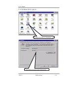
Page 70: ...User s Manual GT 650 Software Setup 5 13 5 4 PCI Ethernet Controller Found 5 4 1 For windows 98 Double click on System High light PCI Ethernet Controller then clicks Properties ...

Page 71: ...User s Manual GT 650 Software Setup 5 14 Select Driver then click on Update Driver Click on Next ...

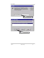
Page 72: ...User s Manual GT 650 Software Setup 5 15 Click on Next Setup PATH from Browse then click on Next ...

Page 73: ...User s Manual GT 650 Software Setup 5 16 Select correct LAN driver for OS by browser Click on Next ...

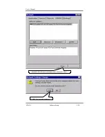
Page 74: ...User s Manual GT 650 Software Setup 5 17 Click on Finish Click on Yes to restart computer ...

Page 75: ...User s Manual GT 650 Software Setup 5 18 5 4 2 For Windows 2000 system Click on System ...

Page 76: ...User s Manual GT 650 Software Setup 5 19 Select Hardware then click on Device Manager Double click on Ethernet Controller ...

Page 77: ...User s Manual GT 650 Software Setup 5 20 Select Driver then click on Update Driver Click on Next ...

Page 78: ...User s Manual GT 650 Software Setup 5 21 Click on Next Click on Next ...

Page 79: ...User s Manual GT 650 Software Setup 5 22 Specify the PATH by Browser Locate the INF file ...

Page 80: ...User s Manual GT 650 Software Setup 5 23 Click on Next Click on Finish ...

Page 81: ...User s Manual GT 650 Software Setup 5 24 Click on Close ...

Page 82: ...User s Manual GT 650 Software Setup 5 25 5 4 3 Windows NT4 0 system Double click Network on Control Panel Add or modify the computer name and workgroup ...

Page 83: ...User s Manual GT 650 Software Setup 5 26 Click on Add Click on Have Disk ...

Page 84: ...User s Manual GT 650 Software Setup 5 27 Entry the Path then click OK Select RTL8139 then click OK ...

Page 85: ...User s Manual GT 650 Software Setup 5 28 Realtek RTL8139 Driver loads automatically then click Close Click Yes to restart computer ...

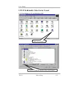
Page 86: ...User s Manual GT 650 Software Setup 5 29 5 5 PCI Multimedia Video Device Found 5 5 1 For Windows 98 and Windows ME Double click on System Select PCI Multimedia Video Device then clicks Properties ...

Page 87: ...User s Manual GT 650 Software Setup 5 30 Select Driver then click on Update Driver Click on Next ...

Page 88: ...User s Manual GT 650 Software Setup 5 31 Click on Next Click Browse to specify PATH ...

Page 89: ...User s Manual GT 650 Software Setup 5 32 Click on Next Click OK ...

Page 90: ...User s Manual GT 650 Software Setup 5 33 Specify the file location then click OK Click on Finish ...

Page 91: ...User s Manual GT 650 Software Setup 5 34 Click on Close Select PCI Multimedia Device then clicks Properties ...

Page 92: ...User s Manual GT 650 Software Setup 5 35 Select Driver then click on Update Driver Click on Next ...

Page 93: ...User s Manual GT 650 Software Setup 5 36 Click on Next Click on Next ...

Page 94: ...User s Manual GT 650 Software Setup 5 37 Click on Next Click on Finish ...

Page 95: ... appear with available options Highlight your option and press Enter Each highlighted option has a help message guide displayed at the bottom of the screen for additional information 4 After you have made your selection and are certain with your choice press ESC A prompt will appear asking if you want to save the configuration Press Y if you want to save The Ethernet Setup Menu also offers three u...

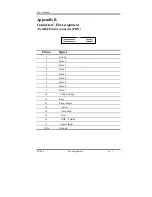
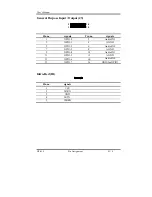
Page 96: ...in Assignment Parallel Printer connector PRN 1 2 25 26 Pin no Signal 1 Strobe 2 Data 0 3 Data 1 4 Data 2 5 Data 3 6 Data 4 7 Data 5 8 Data 6 9 Data 7 10 Acknowledge 11 Busy 12 Paper Empty 13 Select 14 Auto Feed 15 Error 16 INIT Printer 17 Select Input 18 26 Ground ...

Page 97: ...nal Pin no Signal 1 RST 2 GND 3 D7 4 D8 5 D6 6 D9 7 D5 8 D10 9 D4 10 D11 11 D3 12 D12 13 D2 14 D13 15 D1 16 D14 17 D0 18 D15 19 GND 20 N C 21 N C 22 GND 23 IOW 24 GND 25 IOR 26 GND 27 IORDY 28 BALE 29 N C 30 GND 31 IRQ 32 IO CS16 33 A1 34 N C 35 A0 36 A2 37 CS0 38 CS1 39 ACT 40 GND ...

Page 98: ... of FDD 26 pin box header Pin no Signal 1 3 5 5V 7 11 13 19 21 Unused 2 Index 4 Driver Select 6 Disk Change 8 High Density 9 RPM 10 Motor Select 12 Direction 14 Step Pulse 16 Write Data 18 Write Enable 20 Track 0 22 Write Protect 24 Read Data 26 Select Head 15 17 23 25 Ground ...

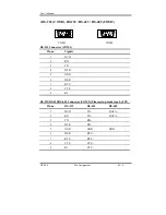
Page 99: ...5 9 COM1 COM2 RS 232 Connector COM1 Pin no Signals 1 DCD 2 RX 3 TX 4 DTR 5 GND 6 DSR 7 RTS 8 CTS 9 RI RS 232 RS 422 RS 485 Connector COM2 Please setup mode type by JP3 Pin no RS 232 RS 422 RS 485 1 DCD TX DATA 2 RX TX DATA 3 TX RX 4 DTR RX 5 GND GND GND 6 DSR RTS 7 RTS RTS 8 CTS CTS 9 RI CTS ...

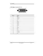
Page 100: ...User s Manual GT 650 Pin Assignment B 5 CRT Display Connector VGA 6 1 5 10 15 11 Pin no Signal 1 RED 2 GREEN 3 BLUE 4 N C 5 GND 6 GND 7 GND 8 GND 9 N C 10 GND 11 N C 12 N C 13 H SYNC 14 V SYNC 15 N C ...

Page 101: ... 6 1 2 3 4 5 6 PS 2 Key board PS 2 Mouse Pin no K B Signals Mini Din Mouse Signals Mini Din 1 KB data MS data 2 NC NC 3 GND GND 4 VCC VCC 5 KB clock MS clock 6 NC NC Ethernet connector RJ 45 LAN Drawing of Ethernet connector RJ 45 Pin no signals 1 TX 2 TX 3 RX 4 NC 5 NC 6 RX 7 NC 8 NC ...

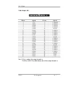
Page 102: ... 14 V I OE31 15 VIN30 16 V I OE32 17 VIN31 18 V I OE33 19 VIN32 20 AGND 21 VIN33 22 V I OE20 23 AGND 24 V I OE21 25 VIN20 26 V I OE22 27 VIN21 28 V I OE23 29 AGND 30 AGND 31 VIN22 32 V I OE10 33 VIN23 34 V I OE11 35 AGND 36 V I OE12 37 VIN10 38 V I OE13 39 VIN11 40 AGND 41 VIN12 42 GND 43 VIN13 44 VCC Note VIN xx is analog video input channel xx V I OExx is Odd Even field information of video inpu...

Page 103: ...J3 1 2 15 16 Pin no signals Pin no signals 1 GPIO 0 2 Audio IN3 3 GPIO 1 4 AGND 5 GPIO 2 6 Audio IN2 7 GPIO 3 8 AGND 9 GPIO 4 10 Audio IN1 11 GPIO 5 12 AGND 13 GPIO 6 14 Audio IN0 15 GPIO 7 16 GND for GPIO Infra Red IR 1 5 Pin no signals 1 VCC 2 IRRX 3 GND 4 IRTX 5 CIRRX ...

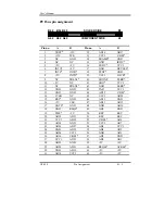
Page 104: ...N1 40 SDONE PERR 10 5V NC 41 SBO VCC3 11 NC PREN2 42 GND SERR 12 GND GND 43 PAR VCC3 13 GND GND 44 AD15 C BE1 14 3VSB NC 45 VCC3 AD14 15 RST GND 46 AD13 GND 16 5V CLK 47 AD11 AD12 17 GNT0 GND 48 GND AD10 18 GND REQ0 49 AD9 GND 19 PME 5V 50 KEY KEY 20 AD30 AD31 51 KEY KEY 21 VCC3 AD29 52 C BE0 AD8 22 AD28 GND 53 VCC3 AD7 23 AD26 AD27 54 AD6 VCC3 24 GND AD25 55 AD4 AD5 25 AD24 VCC3 56 GND AD3 26 AD1...

Page 105: ...s into floppy disk Or copy these two files into the directory you made in hard disk 2 Restart your computer into MS DOS mode or command prompt only for windows go into the directory where the new BIOS file located use the utility AWDFLASH EXE to update the BIOS 3 Type AWDFLASH new bios filename under the prompt 4 Turn off the power after the system updates the BIOS 5 Turn on the power again ...

Page 106: ...tended Functions Data Register I O port address 2Fh or 4Fh After programming of configuration register is finished Exit the extended function mode by writing 0AAh to the Extended Functions Enable Register EFER I O port address 2Eh or 4Eh Extended Functions Enable Registers EFERs After a power on reset the super I O enters the default operating mode Before enters the extended function mode a specif...

Page 107: ...Logical Device Number i e 0x07 to the EFIR and then write the number of desired logical device to the EFDR Secondly write the address of desired configuration register within the logical device to EFIR and then write or read the desired configuration register through EFDR 3 Exit the extended function mode After programming of configuration register is finished Exit the extended function mode by wr...

Page 108: ...interrupt reset Enable or Disable 1 Watchdog Timer is reset upon a Mouse interrupt 0 Watchdog Timer is not affected by Mouse interrupt Bit 6 Keyboard interrupt reset Enable or Disable 1 Watchdog Timer is reset upon a Keyboard interrupt 0 Watchdog Timer is not affected by Keyboard interrupt Bit 5 Force Watchdog Timer time out write only 1 Force Watchdog Timer time out event this bit is self clearin...

Page 109: ...urate logical device 8 configuration register CRF0 mov dx 2eh mov al 07h out dx al point to logical device number register mov dx 2fh mov al 08h device 8 out dx al mov dx 2eh mov al 30h out dx al mov dx 2fh mov al 01h enable device 8 out dx al mov dx 2eh mov al 07h out dx al mov dx 2fh mov al 08h device 8 out dx al mov dx 2eh mov al 0f7h out dx al device 8 CRF7 mov dx 2fh mov al 0c0h out dx al mov...

Page 110: ...econd out dx al bit3 1 counter resolution in 1 minute mov dx 2eh mov al 07h out dx al mov dx 2fh mov al 08h out dx al device 8 mov dx 2eh mov al 0f6h device 8 CRF6 out dx al mov dx 2fh mov al 1fh The value is to control the watchdog out dx al timer 1fh 30 seconds or minutes Exit extend function mode mov dx 2eh mov al 0aah out dx al exit end ...

Page 111: ...User s Manual GT 650 Mechanical drawing E 1 Appendix E Mechanical Drawing ...

Reviews: