


User’s Manual
GT-650 WatchDog Timer D - 1
Appendix D
Watchdog Timer
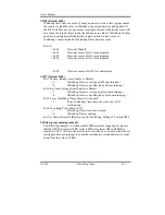
The function of the watchdog timer is to reset the system automatically when
watchdog time out. It contains a one-second resolution down counter (in CRF6
of logical device 8 of super I/O chip) and two Watchdog control registers
(CRF5 and CRF7 of logical device 8). We can uses compatible PnP protocol to
access configuration registers for setting up watchdog timer configuration.
In compatible PnP, a specific value (87h) must be written twice to the EFER,
Secondly, an index value must be written to the Extended Functions Index
Register (I/O port 2Eh or 4Eh same as Extended Functions Enable Register) to
identify which configuration register is to be accessed. (the Logical Device 8).
The designer can then access the desired configuration registers (CRF5, CRF6,
CRF7) through the Extended Functions Data Register (I/O port address 2Fh or
4Fh)
After programming of configuration register is finished, Exit the extended
function mode by writing 0AAh to the Extended Functions Enable Register
EFER (I/O port address 2Eh or 4Eh).
Extended Functions Enable Registers (EFERs)
After a power-on reset, the super I/O enters the default operating mode, Before
enters the extended function mode, a specific value must be programmed into
the Extended Function Enable Register (EFER) so that the extended function
register can be accessed.
Extended Functions Index Registers (EFIRs), Extended Functions Data
Registers (EFDRs),
After the extended function mode is entered, the Extended Function Index
Register (EFIR) must be loaded with index value (02h, 07h~FEh) to access
Configuration Register 0 (CR0), Configuration Register7 (CR07) to
Configuration Register FE (CRFE), and so forth through the extended Function
Data Register (EFDR). The EFIRs are write only register with port address 2Eh
or 4Eh. The EFDRs are read/write registers with port address 2Fh or 4Fh.
Summary of Contents for GT-650
Page 1: ...GT 650 Pentium III Celeron w VGA LAN Audio w Video Capture GPIO Embedded Board User s Manual ...
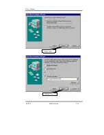
Page 59: ...User s Manual GT 650 Software Setup 5 2 Click on Yes Click on Next ...
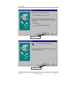
Page 60: ...User s Manual GT 650 Software Setup 5 3 Click Finish to restart computer ...
Page 61: ...User s Manual GT 650 Software Setup 5 4 For Windows NT 4 0 system Click on Yes Click on Next ...
Page 62: ...User s Manual GT 650 Software Setup 5 5 Click Finish to restart computer ...
Page 64: ...User s Manual GT 650 Software Setup 5 7 Click Finish to restart computer ...
Page 67: ...User s Manual GT 650 Software Setup 5 10 Click on Next Click on Next ...
Page 68: ...User s Manual GT 650 Software Setup 5 11 Click Finish ...
Page 74: ...User s Manual GT 650 Software Setup 5 17 Click on Finish Click on Yes to restart computer ...
Page 75: ...User s Manual GT 650 Software Setup 5 18 5 4 2 For Windows 2000 system Click on System ...
Page 78: ...User s Manual GT 650 Software Setup 5 21 Click on Next Click on Next ...
Page 79: ...User s Manual GT 650 Software Setup 5 22 Specify the PATH by Browser Locate the INF file ...
Page 80: ...User s Manual GT 650 Software Setup 5 23 Click on Next Click on Finish ...
Page 81: ...User s Manual GT 650 Software Setup 5 24 Click on Close ...
Page 83: ...User s Manual GT 650 Software Setup 5 26 Click on Add Click on Have Disk ...
Page 88: ...User s Manual GT 650 Software Setup 5 31 Click on Next Click Browse to specify PATH ...
Page 89: ...User s Manual GT 650 Software Setup 5 32 Click on Next Click OK ...
Page 93: ...User s Manual GT 650 Software Setup 5 36 Click on Next Click on Next ...
Page 94: ...User s Manual GT 650 Software Setup 5 37 Click on Next Click on Finish ...
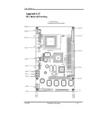
Page 111: ...User s Manual GT 650 Mechanical drawing E 1 Appendix E Mechanical Drawing ...


