User’s Manual
GT-650 Installation 3-2
L
G
S
G
M
7
1
V
6
5
1
6
3
C
T
5
L
G
S
G
M
7
1
V
6
5
1
6
3
C
T
5
L
G
S
G
M
7
1
V
6
5
1
6
3
C
T
5
L
G
S
G
M
7
1
V
6
5
1
6
3
C
T
5
L
G
S
G
M
7
1
V
6
5
1
6
3
C
T
5
L
G
S
G
M
7
1
V
6
5
1
6
3
C
T
5
L
G
S
G
M
7
1
V
6
5
1
6
3
C
T
5
L
G
S
G
M
7
1
V
6
5
1
6
3
C
T
5
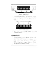
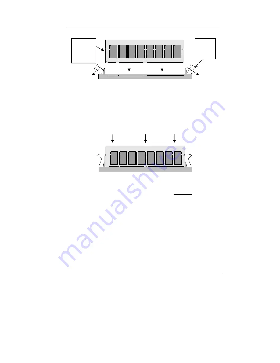
Figure 3-1: DIMM Orientation
3.
Using both hands, press downward and guide the DIMM into socket.
The module release levers will return to their upright position when the
DIMM is completely seated in the socket. The pegs on the tips of the
release levers should align with the notches on the both ends of the
DIMM.
Apply even downward pressure when installing
L
G
S
G
M
7
1
V
6
5
1
6
3
C
T
5
L
G
S
G
M
7
1
V
6
5
1
6
3
C
T
5
L
G
S
G
M
7
1
V
6
5
1
6
3
C
T
5
L
G
S
G
M
7
1
V
6
5
1
6
3
C
T
5
L
G
S
G
M
7
1
V
6
5
1
6
3
C
T
5
L
G
S
G
M
7
1
V
6
5
1
6
3
C
T
5
L
G
S
G
M
7
1
V
6
5
1
6
3
C
T
5
L
G
S
G
M
7
1
V
6
5
1
6
3
C
T
5
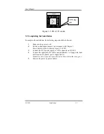
Figure 3-2: DIMM Installation
4.
Repeat Steps 1-3 for the remaining DIMM in DIMM 2. You can install
two DIMMs on the board.
3.2 Installing the CPU
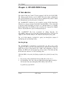
1.
Match key pin on the CPU with key pin of the PGA370 socket. Please
see the figure 3-3 for detail.
2.
To complete the installation, gently press the CPU onto place.
3.
Double-checks the insertion and orientation of the CPU before applying
power. Improper installation will result in permanent damage to the
CPU.
4.
Add the heat sink on the top of CPU properly. It is very important to
have property heat sink for different speed CPU.
Notched
ends of
memory
module
Module
release
levers
Summary of Contents for GT-650
Page 1: ...GT 650 Pentium III Celeron w VGA LAN Audio w Video Capture GPIO Embedded Board User s Manual ...
Page 59: ...User s Manual GT 650 Software Setup 5 2 Click on Yes Click on Next ...
Page 60: ...User s Manual GT 650 Software Setup 5 3 Click Finish to restart computer ...
Page 61: ...User s Manual GT 650 Software Setup 5 4 For Windows NT 4 0 system Click on Yes Click on Next ...
Page 62: ...User s Manual GT 650 Software Setup 5 5 Click Finish to restart computer ...
Page 64: ...User s Manual GT 650 Software Setup 5 7 Click Finish to restart computer ...
Page 67: ...User s Manual GT 650 Software Setup 5 10 Click on Next Click on Next ...
Page 68: ...User s Manual GT 650 Software Setup 5 11 Click Finish ...
Page 74: ...User s Manual GT 650 Software Setup 5 17 Click on Finish Click on Yes to restart computer ...
Page 75: ...User s Manual GT 650 Software Setup 5 18 5 4 2 For Windows 2000 system Click on System ...
Page 78: ...User s Manual GT 650 Software Setup 5 21 Click on Next Click on Next ...
Page 79: ...User s Manual GT 650 Software Setup 5 22 Specify the PATH by Browser Locate the INF file ...
Page 80: ...User s Manual GT 650 Software Setup 5 23 Click on Next Click on Finish ...
Page 81: ...User s Manual GT 650 Software Setup 5 24 Click on Close ...
Page 83: ...User s Manual GT 650 Software Setup 5 26 Click on Add Click on Have Disk ...
Page 88: ...User s Manual GT 650 Software Setup 5 31 Click on Next Click Browse to specify PATH ...
Page 89: ...User s Manual GT 650 Software Setup 5 32 Click on Next Click OK ...
Page 93: ...User s Manual GT 650 Software Setup 5 36 Click on Next Click on Next ...
Page 94: ...User s Manual GT 650 Software Setup 5 37 Click on Next Click on Finish ...
Page 111: ...User s Manual GT 650 Mechanical drawing E 1 Appendix E Mechanical Drawing ...


