7
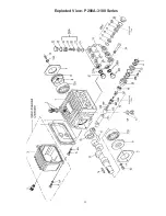
Disassembly sequence of the back end of the P200A-3100 series pump.
1)
Before you begin, drain the oil from the crankcase.
2)
Remove the crankcase cover (3) and o-ring (4) from the crankcase (1). To remove the crankshaft (13),
remove the bearing cover (7) and sight glass (8). Using a rubber mallet, remove the crankshaft axially
through the connecting rods by tapping on the end of the shaft. Be careful not to bend or damage the con
-
necting rods during crankshaft removal.
3)
If the bearings (12A and 12B) and radial shaft seal (11) are still in the crankcase, remove them. Inspect
both bearings and seal for wear and replace if necessary.
4)
Remove the connecting rod (15) and plunger assembly (16). Remove the wrist pin (17) if necessary.
Check the plunger bore in the crankcase for wear. Inspect parts and replace as necessary.
5)
Should you find it necessary to service the plunger assembly (16) you can do so by removing the tension
screw (16C). Replace crush washer (16D).
NOTE: Carefully flatten crush washer before replacing it.
Inspect all parts and replace as necessary.
Reassembly sequence of the P200A-3100 series pump
1)
Reassemble plunger assembly (16) (apply a drop of Loctite to the tension screw (16C) threads) and the
connecting rod (15) with wrist pin (17). Place assemblies in crankcase (1). Install crankshaft through con
-
necting rods again being careful not to bend or otherwise damage the connecting rods.
2)
Replace left and right side bearings (12A and 12B) if they were removed from the crankshaft. Be certain
the bearings are pressed all the way onto the shaft and completely into the crankcase. Replace radial shaft
seal (11), bearing cover (7), sight glass (8), and crankcase cover (3) with its o-ring (4).
3)
If oil seals (19) were removed, replace with seal lip towards crankcase. Lubricate seal before replacing.
4)
Replace seal case (20) with o-rings (21) over plungers. Generously lubricate o-rings and oil seal before
reassembly. Replace drip shield (23B) and v-sleeve (23A) over plungers (16)..
5)
Generously lubricate v-sleeve (23) and assemble into valve casing (26). Assemble weep return ring (25)
and pressure ring (24) over plungers (16). Slide valve casing over plungers and seat firmly. Replace the
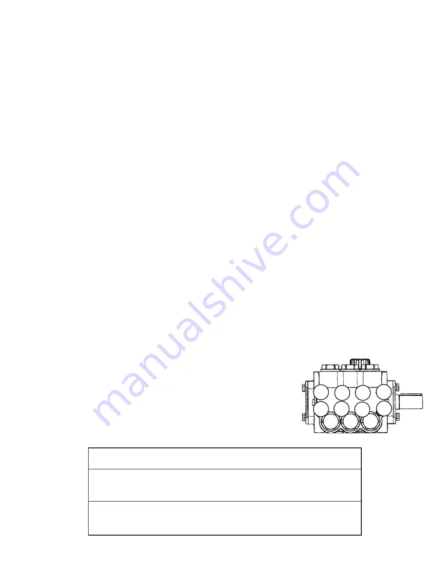
eight socket head cap screws (34) and tighten to 105 inch-pounds in a crossing pattern (see below).
6)
Re-install the six o-rings (31) and the six valve assemblies (27-30), and spacer ring (16D), P230-3100 only.
Now replace the six valve plugs with o-rings (32 and 33) and tighten securely with a 22mm socket wrench
to 33 foot-pounds.
7)
Fill crankcase with 8.1 ounces of oil.
REPAIR INSTRUCTIONS - P200A-3100 SERIES
Bushings
07174
- 24 mm Tapered H Bushing
Pulley & Sheaves
01061
- 7.75” Cast Iron - 1 gr. - AB Section
01062
- 7.75” Cast Iron - 2 gr. - AB Section
Rails
01160
- Plated Steel Channel Rails (L=5.75”x W-1.0”XH=1.812”)
01161
- Plated Steel Channel Rails (L=5.75”x W-1.0”XH=2.50”)
1
2
3
4
5
6
7
8
Pump Mounting Selection Guide

