background image

6

REPAIR INSTRUCTIONS - P200A-3100 SERIES

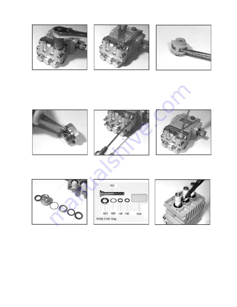
1.  With a 22mm socket 

wrench, remove the (3) 

discharge valve plugs and 

(3) inlet valve plugs (32) 

Inspect the o-ring (33) for 

wear and replace if dam-
aged.

2.  Using a needle nose pliers, 

remove the inlet and dis

-

charge valve assemblies 


(27-30), for P230-3100 only, 

remove spacer (30A), and 


o-ring (31). 

Inspect all parts 

for wear and replace as nec-
essary. 

3.  By inserting a small screw 

driver between the valve 

seat (27) and the valve 

spring retainer (30), the 

valve assembly can be sepa-
rated.

7.  Remove the weep return 

ring (25), pressure ring 

(24), and v-sleeve (23) 

from the valve casing (26). 

Remove the rear v-sleeve 

(23A) from the seal case 

(20). Inspect all parts, in

-

cluding o-ring (21) for wear 

and replace as necessary. 

8.Check surfaces of plunger pipe 

(16B). A damaged surface will cause 

accelerated wear on the seals. De

-

posits of any kind must be carefully 

removed from the plunger surface. A 

damaged plunger must be replaced!  

When replacing the crush washer 
(item 16D), make sure the rolled side 
of the crush washer is placed on the 
ceramic. Prior to installation, care-
fully crush the seal ring on a hand 
press.

9.  If the crankcase oil seals 

(19) are to be replaced, 

they can be removed by 

prying loose with a flat 

screwdriver. Take care not 

to make contact with the 

plunger.  

4.  Apply one drop of Loctite 

243 to the valve plugs (32) 

and tighten to 33 ft.-lbs.

5.  Next, use a 5mm allen 

wrench to remove the 8 

socket head cap screws 

(34).

6.  Carefully slide the valve 

casing (26) out over the 

plungers.  

Summary of Contents for P217-3100

Page 1: ...ications page 5 Repair Instructions pages 6 7 Dimensions back page Warranty Information back page Triplex Ceramic Plunger Pump Operating Instructions Repair and Service Manual Updated 11 11 Nickle Alu...

Page 2: ...rom Giant Industries Inc 4 Run the pump dry approximately 10 seconds to drain the water before exposure to freezing temperatures 1 Prior to initial operation add oil to the crank case so that oil leve...

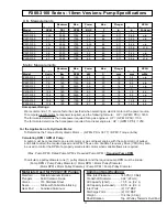
Page 3: ...Common Specifications Max Inlet Pressure 145 PSI 10 Bar Crankshaft Diameter 0 94 24mm Oil Capacity short 7 5 fl oz 0 2 L Oil Capacity extended 9 0 fl oz 0 3 L Inlet Ports 2 1 2 BSP Discharge Ports 2...

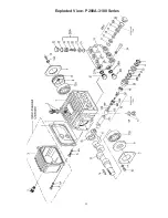
Page 4: ...4 Exploded View P200A 3100 Series...

Page 5: ...p Shield 3 24 07904 Pressure Ring 3 25 08445 0100 Weep Return Ring 316 S S 3 26 06582 3000 Valve Casing 1 26A 07946 0100 Valve Assembly 27 30 31 33 Except P230 3100 6 27 07849 0100 Valve Seat 6 28 068...

Page 6: ...l case 20 Inspect all parts in cluding o ring 21 for wear and replace as necessary 8 Check surfaces of plunger pipe 16B A damaged surface will cause accelerated wear on the seals De posits of any kind...

Page 7: ...reful not to bend or otherwise damage the connecting rods 2 Replace left and right side bearings 12A and 12B if they were removed from the crankshaft Be certain the bearings are pressed all the way on...

Page 8: ...odifications made by the customer or third party 6 The operation of pumps and or accessories exceeding the specifications set forth in the Operations Manuals provided by Giant Industries Inc Liability...

Reviews: