8
7
1. Layout of motherboard
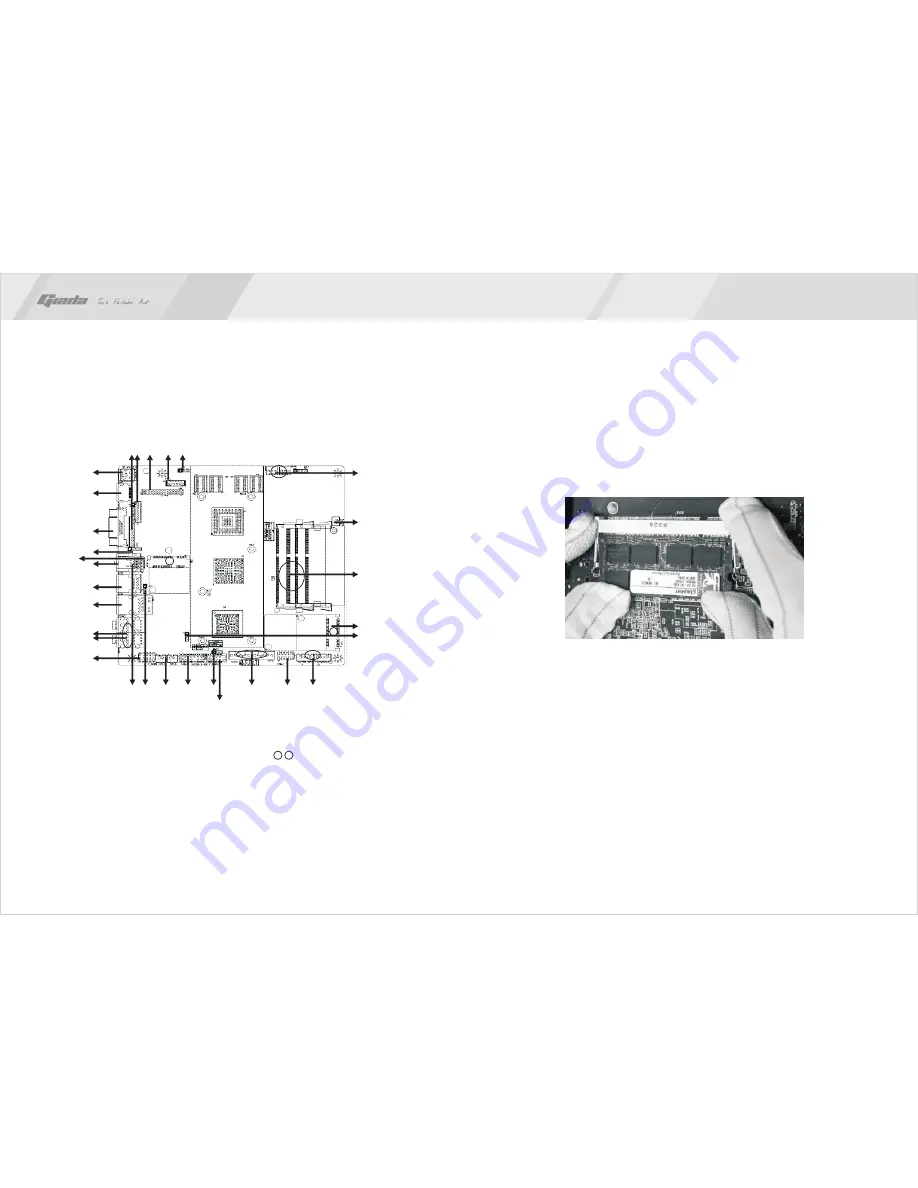
2. Installing memory
Please install the memory in accordance with the following procedures:
·
Align the golden finger of the memory to the groove of the interface slot and
pay attention the concave hole of golden finger should be aligned to the
convex point of the slot.
·
Finally, insert the memory into the interface slot gently. If no error occurs at
the moment, insert the card forward in the slot till the white buckle is
automatically engaged in the concave hole at the two sides of the memory.
www.giadatech.com
1 LVDS POWER
2. LVDS
3. LVDS CONNECTOR
4. VGA-OUT
5. DC-IN
6. HDMI
7. VGA
8.
9. SPDIF
.
USB2.0
10. USB
11. RJ45
12. AUDIO-OUT
13. FRONT AUDIO
14. USB+IR
15. CLR-CMOS
16. F-PANEL
17. SATA0,1
18. COM Port
19. HDD POWER
1
2
3
4
5
6
7
8
9
10
12
13
14 15
16
17
18
19
20
21
22
11
20. 1 2 MI-PCIE
21. Memory slots
22. CPUFAN/SYSFAN
23.LCD Firmware Download connector
24.HDMI DDC Jumper
25.SPDIF Pin
26.REAR USB POWER JUMPER
27.AUTO POWER on
28.SPEAKER
29.5V POWER
1
2
NOTE:
In order to avoid damages to the motherboard or the components, the
user must make sure the power supply to the computer is turned off before the
memory or other component is installed or removed. As the groove is set at the
golden finger of the DDR DIMM, the memory can only be inserted into the slot
with one direction. During installation, the user only needs to align the golden
finger and the dual-channel groove of the interface slot and insert it gently. To
avoid damage, never apply excessive force in that process.
23
24
25
26
27
28
29


