background image

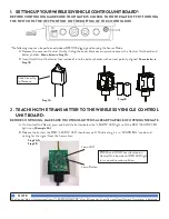
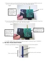
B. Observe that the yellow “DETECT” LED turns ON and the green “XMIT” LED is blinking for 1 second. (Shown in 

Step 3B.) This LED sequence indicates that the Vehicle Sensor has detected the metal and is transmitting.

4.  INSTALLING YOUR WIRELESS VEHICLE SENSOR PROBE AND CONTROL 

UNIT (REMOVE THE (2) C SIZE BATTERIES FOR THIS STEP):

PLAN YOUR INSTALLATION LOCATION FOR THE BEST RADIO FREQUENCY RANGE

A. Make sure your gate is in the CLOSED POSITION and opener is OFF to avoid accidental opening of the gate.
B. Complete steps 1–3 as shown previously.
C. Measure and lay the sensor probe on the ground, next to driveway, and at least 20 feet from the open edge of the 

gate. We recommend placing sensor closest to side of driveway that vehicle exits. Prop up the Control Unit Board 

at least 6

"

 above ground.

D. INSTALL THE BATTERIES INTO THE CONTROL UNIT and wait for the LEDs to stop blinking before continuing.
E. Make sure there are no vehicles or steel or metal objects near the sensor.  Turn the gate opener system on.
F. Move a steel object over the sensor probe (repeating Step 3A) 

OR

 press and quickly release the push button on 

the Vehicle Sensor Control Unit Board to send the “OPEN” signal to the gate. 

G. The green “XMIT” LED on the Vehicle Control Unit Board will start blinking rapidly and the yellow “DETECT” 

LED will stay lit for 1 second to indicate that the “OPEN” signal is being sent.

H. The gate should open when it receives the signal from the wireless vehicle sensor.
I.  Once the desired location is located, 

REMOVE THE BATTERIES FROM THE CONTROL UNIT BEFORE PROCEEDING

.

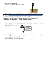
DIG A TRENCH FOR THE SENSOR PROBE AND WIRE:

A. Dig a trench approximately 12

"

 deep to bury the Sensor Probe. In most cases, the sensor should lie in trench 

horizontally and parallel to the driveway.

B. Dig a trench to bury the wire between the Sensor Probe and the Control Unit.

Detect LED

Step 3B

XMIT LED

Dig trench 

approximately 

12 inches deep 

and parallel to 

ground surface

Parallel to driveway

Summary of Contents for AXWV

Page 1: ...t already operates the gate KIT CONTENTS 1 Control Unit with control board to be installed above ground 1 Sensor Probe with 10 foot cable to be buried below ground 1 12 PVC Pipe PREPARING FOR INSTALLATION Must be located at least 20 feet beyond the path of the moving gate Must be located where the driver of the approaching vehicle has clear view of the gate Bury probe approximately 12 deep and as ...

Page 2: ...elow in Step 1B 2 TEACHING THE TRANSMITTER TO THE WIRELESS VEHICLE CONTROL UNIT BOARD BEFORE CONTINUING MAKE SURE YOUR TRANSMITTER IS ALREADY CAPABLE OF OPENING THE GATE A On Control Unit Board press and hold the button below the LEARN LED light until the RED LEARN LED light is on Example 2A B Release the button the RED LEARN LED should remain ON indicating it is in LEARNING mode and waiting for t...

Page 3: ...rd should go OFF indicating the signal is LEARNED 3 TESTING THE SENSOR PROBE A Movesometypeofsteelobjectlikealargescrewdriveralongthevehiclesensor asshownbelowinStep3A RED LED light on Control Unit should go OFF Now you can OPEN your gate with vehicle sensor Step 2C Step 2D Vehicle Sensor Step 3A Screwdriver or other metal object Move screwdriver this way This remote transmitter button currently o...

Page 4: ...efore continuing E Make sure there are no vehicles or steel or metal objects near the sensor Turn the gate opener system on F Move a steel object over the sensor probe repeating Step 3A OR press and quickly release the push button on the Vehicle Sensor Control Unit Board to send the OPEN signal to the gate G The green XMIT LED on the Vehicle Control Unit Board will start blinking rapidly and the y...

Page 5: ... turn ON for 1 second then turn off B Once sensor calibrates for 3 minutes then slowly drive past the Sensor Probe and verify that the wireless vehicle sensor opens the gate C Reinstall the cover for the Control Unit FILL IN THE TRENCH AND HOLE A After verifying that the vehicle sensor is functioning properly TURN OFF the gate opener because a moving shovel can trip the sensor and open your gate A...

Page 6: ...f the FCC Rules These limits are designed to provide reasonable protection against harmful interference in a residential installation This equipment generates uses and can radiate radio frequency energy and if not installed and used in accordance with the instructions may cause harmful interference to radio communications However there is no guarantee that interference will not occur in a particul...

Reviews: