background image

HD50CR-AS


-   8   - 

V1.1


4


ALARMS 

For each detected quantity, two alarm thresholds can be set by the user. The alarm is 
generated if the measured value falls below the lower threshold or rises above the up-
per threshold. 

Exceeding a threshold is signaled: 


acoustically, by means of the internal buzzer (if enabled); 


visually, by lighting the alarm LEDs on the front panel (only for the three meas-
urements associated with the analog outputs); 

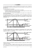
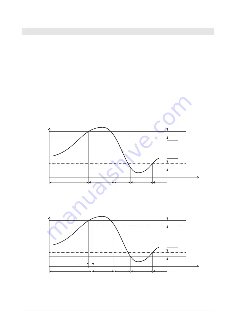
An  alarm  hysteresis  and  a  delay  in  the  generation  of  the  alarm  can  be  configured  for 
each detected quantity. 

The amplitude of the hysteresis is in percentage (0...100%) of the difference between the 
two  alarm  thresholds.  For  example,  if  the  hysteresis  is  2%  (default  value),  the  lower 
threshold is 10 °C and the upper threshold is 60 °C, the hysteresis in °C is equal to (60-
10)x2/100= 1 °C. 

60 °C
59 °C

11 °C
10 °C


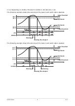
The alarm is generated after the set delay time or immediately if the “

no delay”

 option 

is  selected  (default).  If  the  alarm  condition  disappears  before  the  delay  time  has 
elapsed, the alarm is not generated. 

60 °C
59 °C

11 °C
10 °C


Enabling the Buzzer

 Latch

 option, the buzzer continues to sound even after the alarm 

condition has ceased. 

In the event of an alarm in progress with the buzzer active, the buzzer can be silenced 
for a configurable time. Once the set time has elapsed, the buzzer will resume sounding 

OK 

OK 

Alarm 

Alarm 

OK 

Hysteresis 

Hysteresis 

Upper threshold 

Lower threshold 

OK 

OK 

Alarm 

Alarm 

OK 

Hysteresis 

Hysteresis 

Upper threshold 

Lower threshold 

Delay 

Summary of Contents for Delta OHM HD50CR-AS

Page 1: ...Operating manual Low pressure transmitter data logger HD50CR AS www deltaohm com English Keep for future reference...

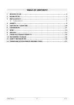
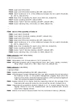
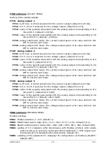
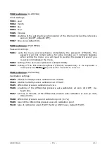
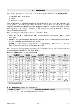
Page 2: ...DESCRIPTION 4 3 INSTALLATION 5 3 1 CONFIGURATION 6 4 ALARMS 8 5 STATISTICAL FUNCTIONS 10 6 CALIBRATION 11 7 MENU 12 8 MODBUS 17 9 TECHNICAL CHARACTERISTICS 23 10 INSTRUMENT STORAGE 26 11 SAFETY INSTRU...

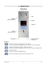
Page 3: ...ectroluminescent display has an inattinic red protection The front keyboard al lows scrolling the real time measurements and configuring the instrument Equipped with a USB port with mini USB connector...

Page 4: ...atistical functions MIN MAX AVG In menu decreases the displayed value or move to the previous parameter Enters the menu In menu confirms the displayed value Cancel the operation or goes back to the pr...

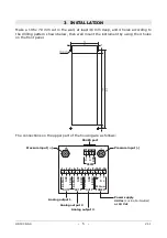
Page 5: ...he 4 holes on the front panel The connections on the upper part of the housing are as follows 12 11 10 9 8 7 6 5 4 3 2 1 0 4 20 mA 0 4 20 mA 0 4 20 mA 0 5 10 V GND GND GND 0 5 10 V 0 5 10 V OUT 1 OUT...

Page 6: ...chapter 7 or via the HD35AP S software The current analog output and the voltage analog output of the same channel 1 2 or 3 are associated with the same quantity The RS485 connection is shown below R...

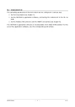
Page 7: ...keyboard see chapter 7 Via the HD35AP S application software connecting the instrument to the PC via USB Via the Modbus RTU protocol and the RS485 connection see chapter 8 The HD35AP S application so...

Page 8: ...s For example if the hysteresis is 2 default value the lower threshold is 10 C and the upper threshold is 60 C the hysteresis in C is equal to 60 10 x2 100 1 C 60 C 59 C 11 C 10 C The alarm is generat...

Page 9: ...UZZER The following example shows the silencing of the buzzer with Latch option enabled 60 C 59 C 11 C 10 C LED BUZZER off off on on off Hysteresis Hysteresis Upper threshold Lower threshold Delay off...

Page 10: ...value of the displayed quantity To scroll the maximum values of the various quantities use the key By pressing FUNC again the instrument shows the minimum value of the dis played quantity By pressing...

Page 11: ...nu connect the front inputs to a low differential pressure generator The differential pressure zero calibration is also possible via the Modbus Coil register with address 72 see chapter 8 At the end o...

Page 12: ...second digit of the password will blink Set the remaining digits in the same way 3 Using keys select a main category in the menu and confirm MENU key 4 If the selected main category has a submenu sel...

Page 13: ...ment index CH1 CH6 default CH1 Set a measurement to OFF to exclude it F300 submenu DISP LOOP VIEW Selection of the quantities to be displayed cyclically Note in the F300 submenu only the quantities to...

Page 14: ...ault OFF F469 buzzer silencing time in minutes 0 1080 default 0 F500 submenu UNIT MEAS MENU Units of measurement F501 temperature unit of measurement C F default C F502 differential pressure unit of m...

Page 15: ...output goes to the value entered Set OFF to exit the test mode F726 analog output test mode The voltage output goes to the value entered Set OFF to exit the test mode F730 analog output 3 F731 0 20 m...

Page 16: ...ng of the user level password default 0000 FA03 locking of the instrument keyboard YES nO default nO If the keyboard is locked keep the MENU key pressed for 7 seconds to unlock it Fb00 submenu CAL MEN...

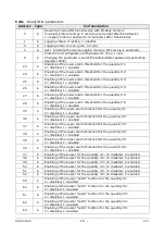
Page 17: ...value expressed as an integer e g if the content of the reg ister is 500 the value is to be intended as 5 00 The commands for requesting units of measurement return an index according to the correspo...

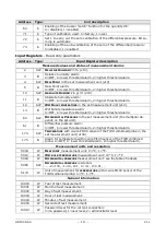
Page 18: ...threshold for the quantity 1 0 disabled 1 enabled 36 b Enabling of the upper alarm threshold for the quantity 2 0 disabled 1 enabled 37 b Enabling of the upper alarm threshold for the quantity 3 0 di...

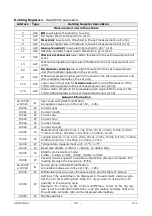
Page 19: ...er threshold alarm 2 higher threshold alarm 60 SW DIFFERENTIAL PRESSURE in the set measurement unit the multiplier de pends on the set unit 61 B Differential pressure alarm 0 OFF 1 lower threshold ala...

Page 20: ...00 General information da 10000 a 10019 B User code with ASCII codification Acceptable values are in the set 32 126 10020 W Current year 10021 W Current month 10022 W Current day 10023 W Current hour...

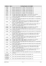
Page 21: ...h the analog output 2 corresponding to 0 4 mA and 0 V 10086 SW Value of the quantity associated with the analog output 2 corresponding to 20 mA and 5 10 V 10087 W Analog output 2 test register the cur...

Page 22: ...alarm delay time in seconds 30010 B ABSOLUTE HUMIDITY alarm hysteresis in g m3 x10 30011 B Absolute humidity alarm delay time in seconds 30012 B WET BULB TEMPERATURE alarm hysteresis in the set measu...

Page 23: ...e of fluid Air and neutral gases Temperature optional Sensor 4 wire Pt100 Measuring range 40 150 C Resolution 0 01 C Accuracy 1 3 DIN Stability 0 1 C year Relative Humidity optional Sensor Capacitive...

Page 24: ...ng interval 1 2 5 10 15 30 s 1 2 5 10 15 30 60 min Logging interval 1 2 5 10 15 30 s 1 2 5 10 15 30 60 min Internal memory Circular management or stop logging if memory is full Number of storable samp...

Page 25: ...HD50CR AS 25 V1 1 Dimensions mm 8 218 151 53 30 70 234 92 8 76 1 5 44 3 1 2 3 3 x4 9 ESC MENU FUNC...

Page 26: ...as the specific measures described in this operating manual The proper operation and the operational safety of the instrument can be ensured on ly under the climatic conditions specified in this manu...

Page 27: ...or 14 mm diameter probes thread M12 1 HD33 Saturated solution to check Relative Humidity probes at 33 RH includes ring adapter for 14 mm diameter probes thread M12 1 HD11 Saturated solution to check R...

Page 28: ...HD50CR AS 28 V1 1 NOTES...

Page 29: ...HD50CR AS 29 V1 1 NOTES...

Page 30: ...HD50CR AS 30 V1 1 NOTES...

Page 31: ......

Page 32: ...rranty included in the manual of the product For any dispute the competent court is the Court of Padua The Italian law and the Convention on Contracts for the International Sales of Goods apply TECHNI...

Reviews: