GHM Messtechnik GmbH
●
Honsberg office
Tenter Weg 2-8
●
42897 Remscheid
●
Germany
Tel49 (0) 2191 9672-0
●
www.honsberg.com
1
Operating manual
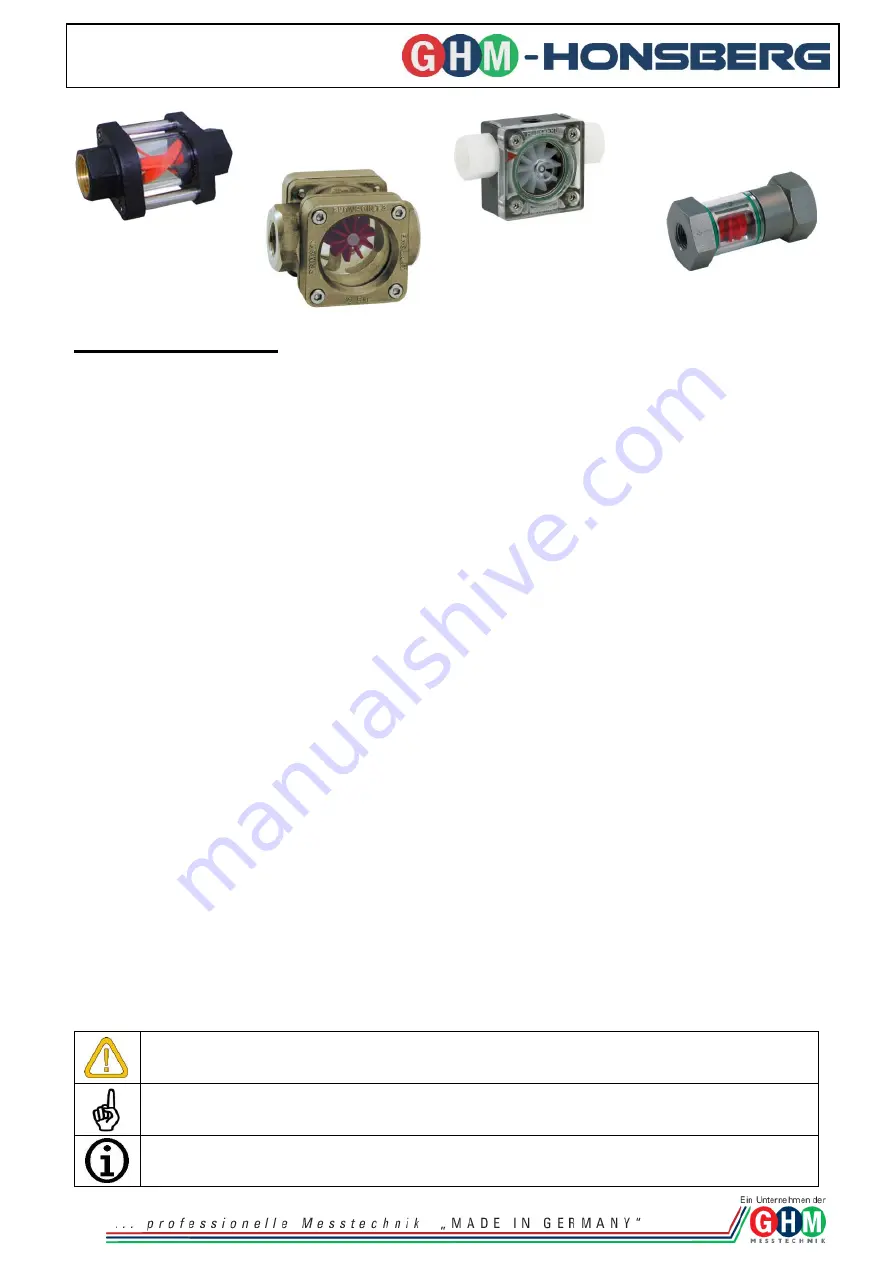
for the flow indicators - rotor, inline structure and turbine: PO, WR1, FR, RM, HV
Table of contents
1
General safety notes, usage ........................................................................................................ 1
1.1
Safety signs and symbols ........................................................................................................ 1
1.2
Safety notes ............................................................................................................................. 2
1.3
Product liability and warranty ................................................................................................... 2
1.4
Standards and guidelines ........................................................................................................ 2
2
Product description ...................................................................................................................... 2
2.1
Active principle ......................................................................................................................... 2
2.2
Product contents ...................................................................................................................... 2
2.3
Appropriate usage ................................................................................................................... 2
3
Structure of the devices ................................................................................................................ 3
4
Assembly and installation ............................................................................................................. 3
4.1
Mechanical assembly ............................................................................................................... 3
5
Activation, operation and maintenance ......................................................................................... 3
5.1
Activation ................................................................................................................................. 3
5.2
Operation/maintenance ............................................................................................................ 4
6
Technical information ................................................................................................................... 4
7
Accessories .................................................................................................................................. 4
8
Device transportation and storage ................................................................................................ 4
9
Return .......................................................................................................................................... 4
10
Disposal.................................................................................................................................... 4
11
Disclaimer ................................................................................................................................. 4
This operating manual must be locally stored so that it can always be accessed.
All procedures described within this operating manual may only be performed by trained personnel
authorised by the operator with corresponding protective gear.
1.1
Safety signs and symbols
Danger signs and symbols are marked as noted below for this operating manual:
1
General safety notes, usage
Warning! Symbol warns of ensuing danger, death, grave bodily injury and/or severe
material damages due to carelessness.
Attention! Symbol warns of possible dangers or harmful situations that arise due to not
observing damage to the device and/or to the surroundings.
Note! Symbol refers to procedures that have an indirect influence on operation due to
carelessness, or which can trigger unforeseen reactions.


