13
13
3.2.2 Configure and Camera Control
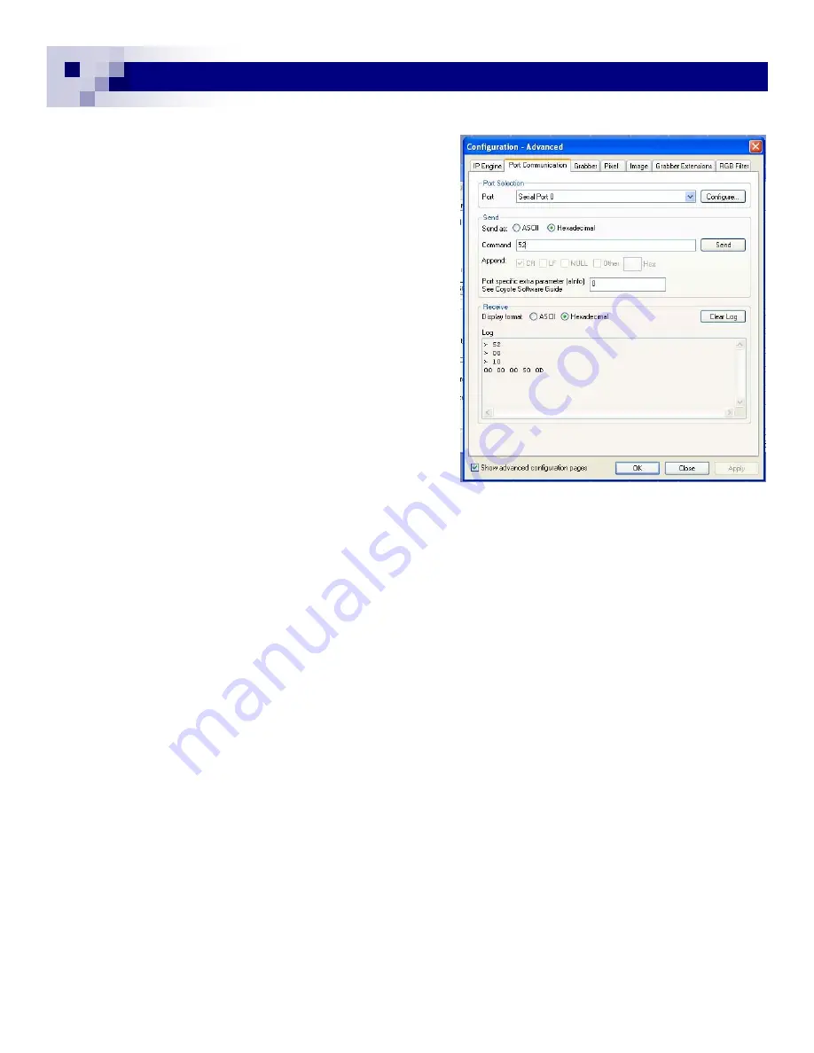
Firstly, open “Configuration Advanced” and set up the
correct image size and pixel information from each tab.
Next, select “Port Communication” tab.
The port is “Serial Port 0” for this camera control. Se-
lect two locations of “Hexadecimal” marks in “Send”
and “Receive”. (Fig. 18)
The camera takes the command as virtual RS-232
control. “
Write
” starts with 57(hex) and “
Read
” is 52,
which are equivalent to ASCII “W” and “R”.
For each 8 bit, command has to be sent. Click “Send”
or hit “Return” at each 8-bit input. (If you are using the
ver. 2.2.0, this is only the way to send command).
For example, the register address of “
Gain Control
“ is
0010 and the data of 32-bit follows. The gain value
resolution is 10-bit and only changes from 0 to 1024
(10-bit). So, sending the maximum gain of 42 dB is;
00 00 03 FF.
Therefore, the sequence of the “
Write”
command is;
57-send, 00-send, 10-send,
00-send, 00-send, 03-send, FF-send.
After the completion, ACK of “06” appears.
With 42 dB of gain, you will see significantly bright but noisy images.
If you want to see the register reading, type “52” <send>, then “00” <send>, “10” <send>. You will see
data of the address and ACK “06”.
In the improved version of 2.3.0, this Port Communication command can be sent as one string.
Type “52” <space> “00” <space> “10“<return>. You will see the same read out as before. If you
change the last “10” with “11”, you will get another data reading of the black level.
It is the same process for the “
Write
” command.
Type “57 00 10 00 00 00 50” <send ( or return)>. For each 8 bit, you have to hit space bar.
Make sure you set back the original gain setting, type “57 00 10 00 00 00 50” <return>.
“Configure” window shows various functions besides the “Port Communication”.
The detailed information is described in section 4.4.
GEViCAM Inc
Fig. 18
Fig. 18
Summary of Contents for GP-151400
Page 39: ...39 39 GEViCAM Inc MEMO ...


