15
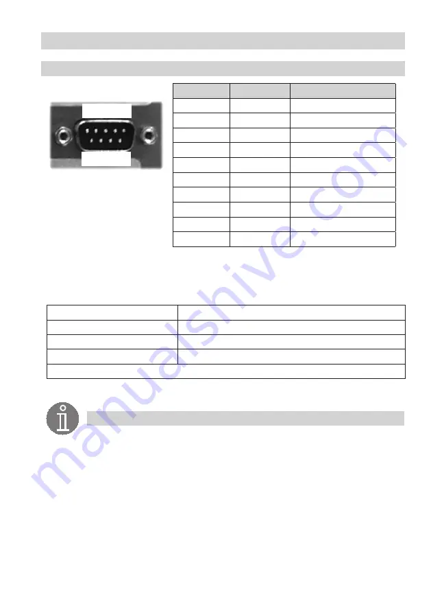
Pin no.
Signal
Description
1
-
-
2
CAN LOW
Negative data signal
3
GND
Signal ground
4
-
5
-
6
GND
Signal ground
7
CAN HIGH
Positive data signal
8
-
9
-
Housing
Case
Cable shield
CAN interface assignment
4
In the control cabinet: Connecting the SPECTOR
control
CANopen devices are connected via the CAN interface.
Use a cable with D-subminiature connector (to DIN 41652) as the data cable.
Use a shielded, multi-core, twisted-pair control cable, e.g. UNITRONIC
®
BUS CAN 2 x 2 x .. mm
2
or RE-
2YCYV-fl 2 x 2 x .. mm
2
, as the bus line.
Cable length
Number of pairs and wire cross-section [mm
2
]
125 m
2 x 2 x 0.34
250 m
2 x 2 x 0.5
335 m
2 x 2 x 0.75
Other lengths available on request
Note
The type and preparation of the data cable have a considerable influence on the electro-
magnetic compatibility (EMC) of the SPECTOR
control
. Therefore, take special care during
connection.
■
Make sure wiring is in line, not in a star!
■
Route the data cable separately from power lines.
■
Use a central earth to prevent differences in potential between system parts.
■
Connect the bus cable shields such as to ensure electrical continuity, and connect to
the central earthing point (CEP).
■
If two or more system components are connected in a CAN bus network, install a
120 Ω terminating resistor (CAN LOW/CAN HIGH module) to the first and last units.
1 2 3 4 5
.
6 7 8 9
.
continued
Summary of Contents for SPECTORcontrol II
Page 18: ...18 Bringing into service Home screens ...
Page 30: ...30 For your notes ...
Page 31: ...31 For your notes ...


