background image

Unpacking Instructions 
 

The Laminar Flow Glovebox is shipped fully assembled in a single crate. All equipment 

must be inspected immediately upon receipt. If there is visible damage to the container or 

unit it must be noted on the receiving documents by the driver. The carrier must then be 

notified to arrange for an immediate inspection to verify the damage to the equipment. If 

damage to the unit is found after it is uncrated (concealed damage), the receiver should 

notify the delivering carrier at once. Do not move the equipment or discard any of the 

shipping materials until a concealed damage inspection is performed. If the carrier will not 

perform this service, please contact the factory immediately at 800- 888-5357. Without this 

inspection of the equipment and packing materials, the freight company may not accept a 

claim for damage or loss and take the position that the damage occurred after delivery. 


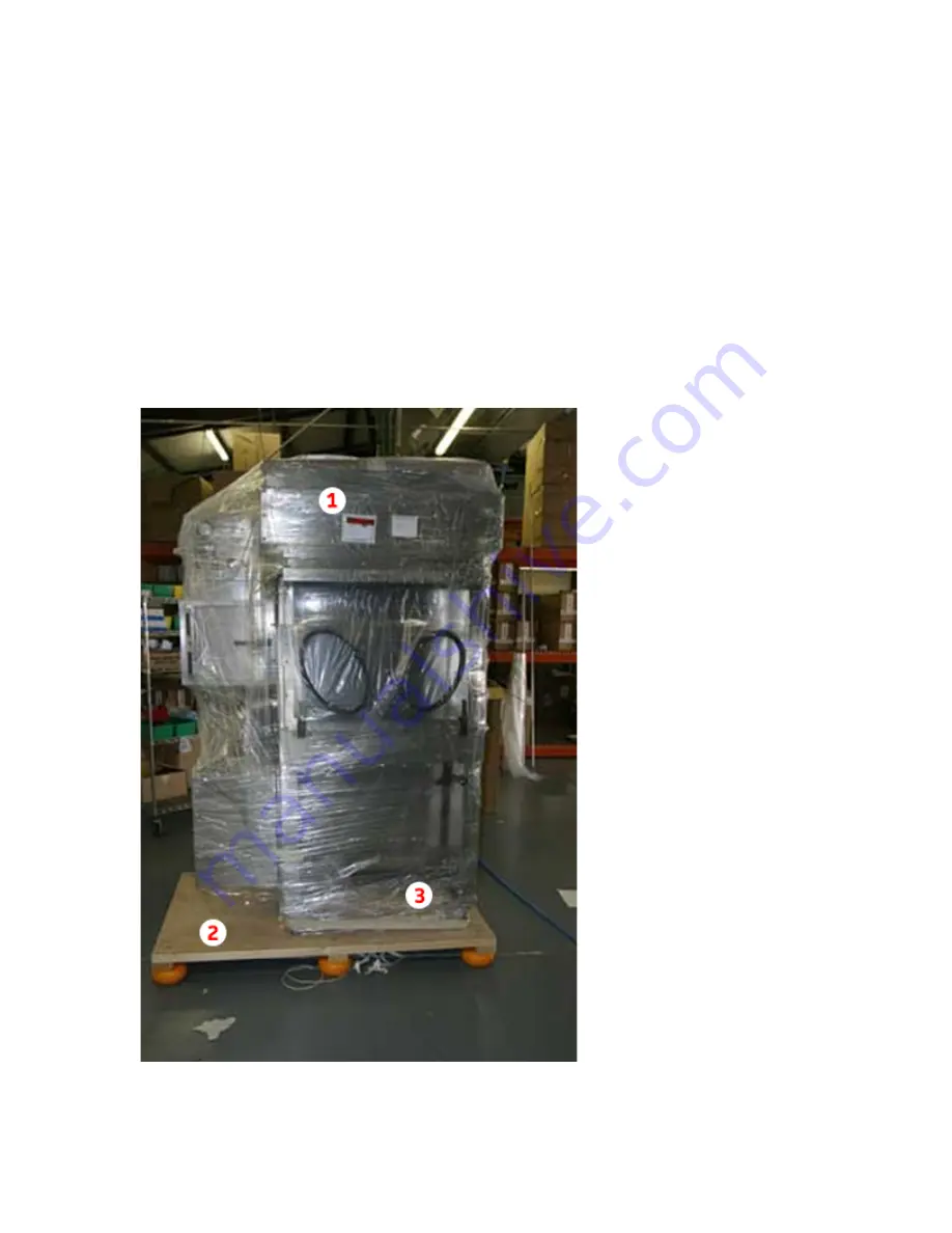
Packaged LFGI 


1. Packing List 

2. Pallet with donut lifts for 

pallet jack 

3. Casters are locked for 

shipping and are touching 

the mounting rack.   


LFGI is on a rack to 

prevent movement during 

shipping.   


DO NOT USE A FORK 

LIFT TO REMOVE LFGI 

FROM THE PALLET 


Extra prefilters are included 

and inside the LFGI.  Store 

these filters for future 

replacement. 


14 

Summary of Contents for LFGI-3USP

Page 1: ...Laminar Flow LFGI CAI or CACI User Manual ...

Page 2: ... GERMFREE 11 Aviator Way Ormond Beach FL 32174 800 888 5357 Phone 386 677 1114 Fax Info Germfree com www Germfree com 2 ...

Page 3: ... VAPORS 10 THEORY 11 HEPA FILTRATION 11 UNIDIRECTIONAL LAMINAR AIR FLOW 12 PRESSURIZATION 12 CONTAINMENT 13 UNPACKING INSTRUCTIONS 14 INSTALLATION 15 ELECTRICAL REQUIREMENTS 16 CERTIFICATION 16 PARTS IDENTIFIER 17 FRONT OF LFGI 17 INSIDE THE WORK AREA 17 INSIDE THE WORK AREA 2 18 SHARPS AND WASTE 18 BACK OF THE CONTROL PANEL 19 CONTROL PANEL 19 CLEANING 20 OUTSIDE THE LFGI 20 INSIDE THE LFGI 20 3 ...

Page 4: ... STAND 31 AUTOMATED COMPOUNDERS 32 ROXTEC GLAND M63 INSTRUCTIONS 33 GLOVES 34 ALARM 34 PROCEDURE FOR CHANGING GLOVES DURING MAINTENANCE 35 SLEEVE CHANGES 38 GLOVE AND SLEEVE INSPECTIONS 39 CLEANING THE LFGI HEAVY DUTY RIGOROUS 40 OUTSIDE THE LFGI 40 INSIDE THE AIRLOCK 40 INSIDE THE LFGI 42 CLEANING THE LFGI BETWEEN PREPARATIONS LIGHT 43 CLEANING AGENTS 45 CLEANING TERMS 46 LFGI USP SPECIFICATION S...

Page 5: ...IRFLOW SET UP 61 SUPPLY VELOCITY 61 ISOLATOR PRESSURE 61 PARTICLE COUNTS 62 FILTER INTEGRITY 62 BACK OF THE CONTROL PANEL 64 REPLACEMENT FILTER SIZES PART NUMBERS 64 SENSOCON CONTROLLER USER MANUAL 66 5 ...

Page 6: ...sterilization 6 Understanding chemical compatibilities for proper decontamination 7 Understanding sterile product preparation and aseptic technique 8 Understanding hazards associated with the products handled in the Laminar Flow Glovebox Isolator 9 Understanding proper maintenance and initial and periodic certification 10 Understanding Federal State and Local applicable professional regulations Th...

Page 7: ...he ambient room air This sealed airlock is then purged with HEPA filtered air to equalize or better the cleanliness level of that contained air to the ISO Class 5 condition of the work area 2 For CACI Model Handling Hazardous Drugs Operators should wear a gown or coat to protect themselves from accidental dermal contact with elements being compounded 3 Operators should always wear gloves when hand...

Page 8: ...or protection Product Protection The Laminar Flow Glovebox Isolator offers the highest level of product protection by providing vertical unidirectional laminar flow HEPA filtered air to the complete work environment The unit utilizes a full width and depth supply HEPA filter above the work surface The entire work area is bathed in HEPA filtered unidirectional mass displaced air This provides a bet...

Page 9: ...olator passes through the exhaust HEPA filter which remove hazardous dust powders aerosols and other particulates All air entering the Laminar Flow Glovebox Isolator passes through the inlet HEPA filter which maintains the barrier Personnel operate in the work area through gloves in a sealed view panel Glove changes can be made while maintaining containment furthering personnel protection 9 ...

Page 10: ...e possible exception of Prions are also removed Personnel and product protection from gas and fumes is not provided by HEPA filtration but limited protection from gas and fumes can be provided by venting or ducting The LFGI can be configured to meet the recommendation for no recirculation and total exhaust of all air exiting the work area made by the NIOSH alert on the handling of hazardous drugs ...

Page 11: ...the entire work area and the exhaust HEPA filter that filters all air exiting the Laminar Flow Glovebox Isolator Additionally there are two HEPA filters located inside the HEPA Purge airlock that filter the purged air All filters are rated to remove particulates and aerosols 0 3 micron in size with a minimum efficiency of 99 99 These filters are even more effective at removing particulates both la...

Page 12: ... providing vertical laminar flow HEPA filtered air to the complete work environment This is the same technology used in the Laminar Flow Workstations and Biological Safety Cabinets that barrier isolators are intended to replace The Laminar Flow Glovebox Isolator utilizes a full width and depth supply HEPA filter above the work surface Any particle laden air is swept from the work area with a wash ...

Page 13: ...s allows a certifier to change the overall pressure of the unit while in place This requires in depth knowledge of the Laminar Flow Glovebox Isolator and its components and should not be attempted by a user Containment The Laminar Flow Glovebox Isolator maintains containment of the work area through a series of filters and its stainless steel construction Joints are welded and polished for easy cl...

Page 14: ...nt or discard any of the shipping materials until a concealed damage inspection is performed If the carrier will not perform this service please contact the factory immediately at 800 888 5357 Without this inspection of the equipment and packing materials the freight company may not accept a claim for damage or loss and take the position that the damage occurred after delivery Packaged LFGI 1 Pack...

Page 15: ...it and is shipped fully assembled After unpacking the unit can be moved into the desired location Unlike an open front hood room air currents do not disrupt the LFGI however proper room placement and room access may be defined by professional and or State regulations The external clean air plenum may be removed if it is discovered that the unit is too wide to fit through a door The Prefilter housi...

Page 16: ...ormance was tested and documented before shipping It requires certification after the unit has been installed and prior to operation This is especially important after transportation of the LFGI from our factory to your facility The purpose of this retesting is to verify that the HEPA filters airflows and pressures are within limits and the unit is performing properly It is always a good idea to r...

Page 17: ...port 8 Viewing Panel Lift 9 Locking View Panel Latch 10 Sharps and Waste Removal Tubes 11 Exhaust HEPA Filter Access Panel 12 Foot Rest 13 Hydraulic Height Adjustment Handle 14 Locking Casters Inside the Work Area 1 Exhaust HEPA Filter 2 Sliding Work Tray 3 Return Air Grilles 4 Electrical Outlet 5 Inner Airlock Door 6 Sharps Tube 7 Waste Tube 17 ...

Page 18: ...ffuser Protector Sharps and Waste 1 Outside of the Airlock 2 Sharps Tube 3 Waste Tube will come with a cover and a clamp that can be removed if this feature is to be used Clamp can be used to secure waste bags 4 Adjustable Sharps Collector Shelf 5 OPTIONAL Stainless Garbage Can 6 OPTIONAL Sealed Sharps Container 7 OPTIONAL Sealed Waste Container 18 ...

Page 19: ... Blower Power Cord 5 Light Housing Power Cord 6 Exhaust Blower Power Cord 7 Work Area Outlet Power Cord 8 Airlock Supply HEPA Filter Cover Control Panel 1 Minihelic Gauge for Supply HEPA filter 2 Digital Work Area Pressure Gauge 3 Light Switch 4 Circuit Breaker 5 Main LFGI Blower Power 6 Purge Start Button 7 Purge Operation Light 19 ...

Page 20: ...disinfectant approved on surfaces for critical environments and controlled areas If the LFGI runs under Positive Pressure open the front access window and allow the LFGI to continue running during cleaning process If the LFGI is under negative pressure the front access window should NOT be opened for cleaning See the Appendices for more detailed instruction Operation Safety and Additional Training...

Page 21: ...8 Clean inside the work area rigorously Please refer to the Appendix on this topic 9 Ensure the stoppers for the trash tubes and sharps are seated in place 10 Close the work area latches and lock if so desired Note the location of the key if removed 11 Wipe down the outside of the LFGI Please refer to the Appendix on this topic 12 Ensure the prefilter is seated properly in its frame at the top of ...

Page 22: ...refer to the Appendix on this topic 3 Ensure both airlock doors are latched 4 Place Sharps collectors as instructed in the section on this topic 5 Attach waste collectors to the discharge tube utilizing either the provided clamp or alternate method tape or elastic for example 6 Clean the inside of the work area rigorously Please refer to Appendix on this topic 7 Ensure the stoppers for the trash t...

Page 23: ...ock Operation The Airlock provides a sealed transfer area between the work area and the ambient room conditions The sealed doors are fitted with adjustable compression hinges to ensure a tight seal against cross contamination The Airlock is equipped with a HEPA purge function to clean the air trapped in the sealed transfer area A blower inside of the control panel pulls air out of the airlock This...

Page 24: ...allows items to easily be brought into the work area reducing operator strain Regular cleaning of the airlock is recommended don t forget to clean under the tray Usage Do not lean materials against the back or front wall as they will block the return air grills operate without gloves or sleeves open both airlock doors at the same time open the front viewing panel when compounding hazardous drugs I...

Page 25: ...remove surface contamination before placing them in the airlock follow all existing internal procedures and policies if you wouldn t do it in a laminar flow workstation or a biological safety cabinet you shouldn t do it in an LFGI Practice Proper Aseptic Technique The Barrier Isolator family of equipment is no different than that of the Laminar Flow Workstation or the Biological Safety Cabinet the...

Page 26: ...k of overflowing a collector All institute regulated safety policies should be followed when handling sharps To move the shelf simply tilt up the outside edge of the shelf to release the bottom tabs from the slotted track The top shelf tabs are notched and will require a push up from the bottom of the shelf This system is equivalent to the casework found in many pharmacies and allows for many diff...

Page 27: ...ted A Stainless Steel Garbage Can is available as an option Never fill the bag completely full allow enough space to seal To remove the bag first cap the Discharge Tube from inside the work area next twist or constrict the bag below the Discharge Tube then clamp shut this area with tape or plastic wire ties After the bag is sealed it can be detached from the Discharge Tube This method of bag remov...

Page 28: ...ver circumstances beyond GERMFREE s control nor problems caused by failure to follow the operating instructions in the GERMFREE equipment manuals THIS WARRANTY DOES NOT APPLY WHEN FAILURE IS DUE TO SHIPPING DAMAGE ACCIDENT ALTERATION MODIFICATION UNAUTHORIZED SERVICE MISUSE ABUSE USE WITH INCOMPATIBLE ACCESSORIES OR ATTACHMENTS FAILURE TO FOLLOW GERMFREE S OPERATION MAINTENANCE OR REPACKING INSTRU...

Page 29: ...gence or other act Maintenance Typical life span of a glove sleeve is 6 months and GERMFREE recommends that they be changed at that interval See the appendix Glove Sleeve change for instruction Typical life span of a prefilter is 3 months but differing room conditions can require replacement more or less frequently During the first 3 months of operation the pre filter should be checked once per mo...

Page 30: ...rongs in line with the loading slot 5 Slide the bulb free 6 Lower the end of the bulb carefully out of the socket When one end is free pull slightly and the other end should come out also 7 Set the old bulb aside and lift a new bulb into the fixture 8 Hold the bulb horizontally and rotate the new bulb until the prongs on each end are lined up with the grooves in the socket 9 Insert the prongs in t...

Page 31: ...in this situation can range from 0 05 if the exhaust blowers are left on to upwards of 2 w c if the exhaust blowers are turned off and the HEPA filter is moderately loaded with particulate Ensure static capacity of the external blower can also accommodate the static imparted by the ducting used The LFGI has a height adjustable stand and to retain this feature we recommend that the portion of ducti...

Page 32: ...you are installing automated compounding equipment please contact GERMFREE for your options The next page gives instructions on how to use the sealed cable pass through if your unit is so equipped You will find the vial of lubricant that is mentioned in the instructions in your cleaning kit Use caution when setting the pass through up as it is mounted in the plastic side panel Replacement cable mo...

Page 33: ...33 ...

Page 34: ... factory before shipping Dramatic drops in pressure indicating possible containment failure are alarmed Alarms will sound when operating work area pressures are between 0 05 and 0 05 inches water column w c Normal work area pressures are 0 1 0 025 inches w c in either positive or negative overall pressures Troubleshooting for Alarm Sounding Cause Corrective Action Glove Rip Tear Removal Replace Gl...

Page 35: ...side 2 Glove O rings rubber rings that can stretch to fit around the GOS 2 Sleeve O rings rubber ring that can stretch to fit around the 10 gloveport 1 Pull the Glove and Sleeve out of the work area so that the sleeve is inside out and pull the existing glove and securing O rings off Glove Over Sleeve 2 Fold the sleeve back over the GOS so that the end of the sleeve is even with the end of the GOS...

Page 36: ...love O Ring 4 Stretch the new glove cuff with both hands before trying to stretch it over the GOS will sometimes make the task easier as well as identify weaknesses in the glove before you get it into the work environment Place the glove through the opening with the thumb pointing upward Then stretch the glove over the GOS ring ...

Page 37: ...37 5 Take the second Glove O ring and slide it over the glove securing it in the GOS groove closest to you Glove O Ring 6 Push the entire glove and sleeve back into the work area ...

Page 38: ...e new glove trapped behind it 9 With two fingers carefully work the old glove off of the GOS from inside the work area It will begin to come free in one spot Work the free spot around the perimeter of the GOS removing the old glove 10 Dispose of the old glove through the waste tubes and push a hand into the new glove Sleeve Changes As seen in this picture there are two grooves on the LFGI glovepor...

Page 39: ...ction of all glove and sleeve surfaces is recommended at the beginning and end of each day Any tears or punctures would require a replacement If the unit is operating and is under pressure the operator can run a hand on all surfaces to feel for any air moving into or out of the work area through imperfections in the surfaces Soap solution can also be used If the LFGI has pressure the soap will bub...

Page 40: ...urface off Raise the stand at least 3 inches from bottom position to wipe down the caster cross supports NEVER spray cleaner of any type directly at the control panel located above the airlock Always spray onto a clean wipe and then wipe the surface switches and knobs Inside the Airlock 1 Open the outer airlock door Spray a clean wipe with disinfectant cleaner and wipe the top HEPA filter protecto...

Page 41: ...7 Repeat steps 1 6 using sterile water to rinse any disinfectant away 8 Repeat steps 1 6 using 70 IPA to sterilize the surfaces and run a purge cycle 41 ...

Page 42: ...rokes wipe top to bottom working downward toward the work surface Be sure to clean the entire airlock door surface that is exposed to the inside of the work area including the handle 5 Slide the left tray over the right tray spray the interior bottom surface of the isolator Clean by wiping from the back to the front using overlapping strokes Be sure to clean the sides and back under the sliding wo...

Page 43: ... us at 800 888 5357 for more information Cleaning the LFGI between preparations Light Sanitizing the LFGI work area between preparations is recommended to reduce the chances of cross contamination 70 Isopropyl Alcohol is the most recommended agent for this task 1 Open only the outer door of the airlock Spray a clean wipe with alcohol and wipe the top and back HEPA filter covers 2 Spray the remaini...

Page 44: ...If all materials are wiped down prior to placement in the airlock it should remain clean for a number of preparations in a row 44 ...

Page 45: ...ex Quaternary Ammonium Compounds QUATS Ordinary housekeeping of floors furniture walls bactericide fungicide viricide not as effective as phenols Quatsyl Coverage 258 End Bac Hi Tor Decon QUAT 100 By Veltek Lysol IC Alpha Lemon QUAT by Alphasource 2 W W Sodium Hypochlorite 1 W W 0 9 Sodium Thiosulfate Cleans and inactivates anti cancer drugs on chemotherapy work surfaces Surface Safe This list is ...

Page 46: ...ctivity To cleanse something so as to destroy or prevent the growth of disease carrying microorganisms To free from infection especially by destroying harmful microorganisms Sanitization That part of decontamination that reduces viable microorganisms to a defined acceptance level normally achieved by using a chemical agent or heat To make sanitary as by cleaning or sterilizing if the apparatus is ...

Page 47: ...The American Heritage Dictionary of the English Language Fourth Edition copyright 200 by Houghton Mifflin Company 47 ...

Page 48: ...s All stainless steel construction both inside and out with a pharmaceutical grade finish 316L Stainless steel work trays slide over one another and are removable to facilitate easy clean up under the work deck All viewing panels are stainless steel framed Acrylic Front viewing panel is top hinged and self supporting for easy access to the work area for cleaning and equipment ingress All filter di...

Page 49: ...loveports have a 3 arm rest to reduce operator fatigue Large viewing panel is at an angle to reduce glare and operator strain Integrated foot rest Configuration Options Overall work area pressure can be either positive or negative and can be altered in place by a certifier Antechamber can be left or right handed or can be installed on both sides Waste and sharps removal tubes can be left or right ...

Page 50: ...N A Up to 2 inches w c depending upon configuration Weight Net Weight 525 lbs Shipping Weight 655 lbs SECTION III OPTIONAL EQUIPMENT AND ACCESSORIES CONSULT YOUR SALESPERSON FOR PRICING LFGI A80 Ergonomic task chair with anti bacterial and anti microbial vinyl covering various colors LFGI A85S Stainless steel cleaning handle with pivot head Accepts lint free mop heads LFGI A85M LFGI A8E Electrical...

Page 51: ...SECTION IV UNIT DIAGRAM Made in the USA and available for purchase on the GSA 51 ...

Page 52: ...inless steel work trays slide over one another and are removable to facilitate easy clean up under the work deck All viewing panels are stainless steel framed Acrylic Front viewing panel is top hinged and self supporting for easy access to the work area for cleaning and equipment ingress All filter diffuser guard panels are removable for easy cleaning Straight sides and back maximize work area to ...

Page 53: ...rest Configuration Options Overall work area pressure can be either positive or negative and can be altered in place by a certifier Antechamber can be left or right handed or can be installed on both sides Waste and sharps removal tubes can be left or right handed or can be installed on both sides Three available exhaust options that can be factory set or changed by a certifier in place Filtration...

Page 54: ...25 lbs Shipping Weight 755 lbs SECTION III OPTIONAL EQUIPMENT AND ACCESSORIES CONSULT YOUR SALESPERSON FOR PRICING LFGI A80 Ergonomic task chair with anti bacterial and anti microbial vinyl covering various colors LFGI A85S Stainless steel cleaning handle with pivot head Accepts lint free mop heads LFGI A85M LFGI A8E Electrical Height Adjustment requires additional plug in LFGI A83 Stainless steel...

Page 55: ...55 ...

Page 56: ...inless steel work trays slide over one another and are removable to facilitate easy clean up under the work deck All viewing panels are stainless steel framed Acrylic Front viewing panel is top hinged and self supporting for easy access to the work area for cleaning and equipment ingress All filter diffuser guard panels are removable for easy cleaning Straight sides and back maximize work area to ...

Page 57: ...rest Configuration Options Overall work area pressure can be either positive or negative and can be altered in place by a certifier Antechamber can be left or right handed or can be installed on both sides Waste and sharps removal tubes can be left or right handed or can be installed on both sides Three available exhaust options that can be factory set or changed by a certifier in place Filtration...

Page 58: ...25 lbs Shipping Weight 955 lbs SECTION III OPTIONAL EQUIPMENT AND ACCESSORIES CONSULT YOUR SALESPERSON FOR PRICING LFGI A80 Ergonomic task chair with anti bacterial and anti microbial vinyl covering various colors LFGI A85S Stainless steel cleaning handle with pivot head Accepts lint free mop heads LFGI A85M LFGI A8E Electrical Height Adjustment requires additional plug in LFGI A83 Stainless steel...

Page 59: ...59 ...

Page 60: ...le preparations and potentially hazardous pharmacy drugs The LFGI USP incorporates a more service friendly platform The LFGI allows for all service and maintenance functions to be performed from the front of the unit side access makes the job even easier The LFGI USP has two Main HEPA filters which require an integrity test and two airlock HEPA filters that are verified in place with a particle co...

Page 61: ...rear of the control panel to set digital pressure gauge to the proper work area pressure as indicated above If further adjustments to the velocity are required a clockwise adjustment of either speed control will always increase air velocity while each one will have an opposite effect on the work area pressure A counterclockwise adjustment increase motor speed of the exhaust blowers will lower over...

Page 62: ...ly and one below exhaust see figure 1 The Supply HEPA filter should be scanned with a Photometer while challenged with DOP or equivalent The aerosol challenge can be introduced to the upstream side of the HEPA filter through the supply blower inlet An upstream challenge can be read through the port opposite the LFGI control panel by removing the hex head plug If access to the side of the unit is n...

Page 63: ...Fig 2 Air recycle plenum connection tip removed 63 ...

Page 64: ...er Sizes Part Numbers LFGI PF3 LFGI 3USP Prefilter 18x37x1 12 PKG PKG LFGI HF3S N LFGI 3USP Supply HEPA 24x36x3 EA LFGI HF3E N LFGI 3USP Exhaust HEPA 12x24x6 EA LFGI PF4 LFGI 4USP Prefilter 18x45 5x1 12 PKG PKG LFGI HF4S N LFGI 4USP Supply HEPA 24x48x3 EA LFGI HF4E N LFGI 4USP Exhaust HEPA 12x36x6 EA LFGI PF6 LFGI 6USP Prefilter 18x69 5x1 12 PKG PKG LFGI HF6S N LFGI 6USP Supply HEPA 24x72x3 EA LFG...

Page 65: ...ial Pressure Gauge We strongly recommend that you consult Germfree Customer Support before any adjustments are made Germfree has a general access code 6756 This would unlock the settings if asked Generally this code is entered at the factory and would remain unlocked 65 ...

Page 66: ...Bulletin 102 0 Installation and Operation Manual Series A3 and A4 Differential Pressure Controller Sensocon Inc Phone 863 248 2800 Fax 863 248 2798 www sensocon com ...

Page 67: ... Specifications 1 3 Dimensional Drawings 2 Installation 2 1 Mounting 2 2 Pressure Connections 2 3 Electrical Connections 3 Operation 3 1 Display 3 2 Key Function 4 Programming 4 1 Menu Structure 4 2 Security Level 4 3 Main Menu 4 4 Set Up Menu 4 5 Secure Menu 5 Other Features 5 1 Moving Program Variables 5 2 Opti Link 5 3 Limited Warranty ...

Page 68: ...utput and improved accuracies There is also a low cost weatherproof cover available for outdoor applications Example A3110 06 Description Model A Round Panel Mount Housing 3 LED display process arch LCD Display 4 LED display process arch OLED Control 1 Control 2 SPDT relays 0 None Transmitter 1 4 20 mA 0 1 Accuracy 1 0 50 01 0 0 50 02 0 1 03 0 2 04 0 3 05 0 4 06 0 5 07 0 8 08 0 10 09 0 15 10 0 20 ...

Page 69: ...ce with optional cover the entire product is weatherproof Relays 2 SPDT 8 Amps 250 VAC 5A 30 VDC Electrical Connections screw terminals Response Time 100 ms Display 4 Digit red LED digits LCD or OLED programming display Process Connection Push on connection for 3 16 tubing Agency Approvals Pending UL C UL CE Patents Pending Custom calibrations including improved accuracy and improved thermal effec...

Page 70: ...control with the provided gasket through the hole and secure it to the panel with the provided mounting tabs and screws Retrofitting old technology is also easy with the Series A3 and A4 They have been designed to fit in industry standard holes ranging from 4 9 16 to 4 13 16 so simply remove the old device and insert the new control into the existing cut out 2 INSTALLATION 2 1 Mounting ...

Page 71: ...he weather proof cover has been attached the control can be mounted to any flat surface with the four mounting screws provided with the cover Flush Mounting with Weather Proof cover The Series A3 and A4 can also be flush mounted with a weather proof cover The procedure is the same as above but utilizes two extra long mounting screws provided with the weather proof cover for the bottom two panel co...

Page 72: ...the front display will give a positive value If the HI connection has a lower absolute value than the LO connection the front display will give a negative value NOTES 1 Supply Voltage is universal from 16 265VAC or VDC 2 For internally sourced 4 20 mA loop maximum loop resistance is 750 Ω for externally sourced loop at 36 VDC maximum loop resistance is 1800 Ω 3 Isolation Relays 1000 VAC to all oth...

Page 73: ...show either 3 or 4 digits based on the users preference The LCD or OLED display is used for programming and displaying the unit of measure and up to 4 other user selected program parameters The LED indicators for SP1 SP2 and Alarm give indication when the parameter is in the actuated state The A3 and A4 have four buttons located on the face of the control used for programming There is an up arrow ...

Page 74: ...he accept button for three seconds this will accept the change and take you back to the menu you were currently in At any point while in a parameter change screen you can hold the cancel button for one second to return to the previous menu without accepting a change to that parameter To manually reset the alarm after an alarm condition has occurred if this feature is used hold the right and left a...

Page 75: ...p value Screen Saver Saver Off On Contrast Contr N lo N med N hi I lo I med I hi K Factor Kfact value Duct Shape Xsect circ rect Duct Diameter diam value Duct Width X dim value Duct Height Y dim value Zero Zero Reset Span Span value Reset Access Access Main Set up Secure none Factory Default Reset No Yes Process Output Lo pol value Process Output Hi poh value Secure Menu Current Power source P S O...

Page 76: ... Set Point is selected there will be no parameters for Set Point 2 or Alarm in the programming 1 Set Point 1SP For control with one SPDT relay 2 Set Point 2SP For control with two independent SPDT relays Set Point Alarm SPAL For control with one SPDT relay and one alarm relay Alarm AL For alarm operation only Set Point Settings Set 1 Set 2 Each set point can be entered as a high and low value for ...

Page 77: ...OFF OFF ON ON ON Relay Action Direct Acting Reverse Acting DB direct acting DB reverse acting Actuation 1 act 2 act The actuation parameter determines whether the relays will react to increasing or decreasing pressure This parameter also affects the status of the LED indicators on the front of the gauge The above graphs illustrate the differences Direct The relays turn on with increasing pressure ...

Page 78: ...e the relay when the process is below the low alarm set point The high and low alarm can be used together so the alarm relay is actuated when the process is above or below the high alarm and low alarm set points respectively The selection will dictate which alarm parameters are shown in the Main Menu The below figure shows the three alarm types High Alarm hi High alarm Low Alarm lo Low alarm High ...

Page 79: ...ed since the last time it was reset value Allows the user to manually reset the value Mode Mode The control is capable of measuring and displaying pressure velocity or flow For velocity and flow a flow sensing device such as a pitot tube or orifice plate with a know flow coefficient is required For flow it is also necessary to know the dimensions of the duct that the flow is being measured in so t...

Page 80: ...40 0 036 0 074 1 868 2 491 249 1 0 249 0 578 2 000 0 167 50 80 5 080 0 072 0 147 3 737 4 982 498 2 0 498 1 156 3 000 0 250 76 20 7 620 0 108 0 221 5 605 7 473 747 3 0 747 1 734 4 000 0 333 101 6 10 16 0 145 0 294 7 473 9 964 996 4 0 996 2 312 5 000 0 417 127 0 12 70 0 181 0 368 9 342 12 45 1245 1 245 2 890 8 000 0 667 203 2 20 32 0 289 0 588 14 95 19 93 1993 1 993 4 624 10 00 0 833 254 0 25 40 0 3...

Page 81: ...ntrast Contr This allows the image and contrast of the programming display to be adjusted Normal low N lo Normal image low contrast Normal medium N med Normal image medium contrast Normal high N hi Normal image high contrast Inverted low I lo Inverted image low contrast Inverted medium I med Inverted image medium contrast Inverted high I hi Inverted image high contrast K Factor Kfact For flow and ...

Page 82: ...revent tampering Once this parameter is set a security code must be entered to regain access to the locked menus as shown in the below table This feature can be used in conjunction with moving program variables section 5 1 to grant or restrict access to specific variables Secure menu Secure Selecting Secure will give the user access to all menus Set up menu Set up Selecting Set Up will give the us...

Page 83: ...current loop The programming menu can be fully customized by the user Parameters can be moved from one menu to another This allows the user to reorganize the menu structure to better fit their needs or to put unused or unwanted parameters in one menu and then lock that menu so that those variables can not be accessed To move a program parameter to another menu highlight the parameter to be moved a...

Page 84: ...te the program has been successfully uploaded to the control LIMITED WARRANTY SENSOCON warrants its products to be free from defects in materials and workmanship for a period of one 1 year from the date of shipment subject to the following terms and conditions Without charge SENSOCON will repair replace or refund the purchase price at SENSOCON s option products found to be defective in materials o...

Page 85: ... 863 248 2800 www sensocon com 20 Installation and Operation Manual Series A3 A4 ...

Reviews: