45
EM61MK2 Data Logging System (DAS70/61MK2)
Appendix A
Appendix A
Appendix A
Appendix A
Appendix A
AAAAA.1 Using the EM61MK2A with a GPS R
.1 Using the EM61MK2A with a GPS R
.1 Using the EM61MK2A with a GPS R
.1 Using the EM61MK2A with a GPS R
.1 Using the EM61MK2A with a GPS Receiver
eceiver
eceiver
eceiver
eceiver
The EM61MK2A program accepts input from GPS receiver that stream NMEA-0183 compatible
data. through their output port. The program uses two NMEA messages: GGA and GSA. The
entire GGA message is written to the EM61MK2 data file, while the GSA message is used only to
display PDOP index on the logger screen.
The GPS system means (control device, receiver panel, or manufacturer software) must be used to
set GPS receiver communication parameters, to specify frequency of GPS output, and number and
type of NMEA messages sent by the GPS system output port. Any GPS system can send various
NMEA messages.
It is important to select only two messages (GGA and GSA) that are actually
used by EM61MK2A.
The program will accept any GPS string sent by the GPS receiver, however
it uses time to process GPS data that is not being used. Therefore, selecting a larger number of
NMEA messages for GPS output will result in slower data acquisition of EM61MK2A. Normally,
the EM61MK2A running in Allegro (or EM61MK2P in Pro4000) logger uses less than 100 ms to
process and record GPS data from two NMEA messages, GGA and GSA.
Only message GGA is necessary to position EM61MK2 data. If message GSA is not available in a
particular system, the EM61MK2A will function and record position data based on GGA message.
Lack of GSA message will result in PDOP index displayed as Not Available (N/A) on the logger
display. Using message GGA alone will also result in slightly faster operation of the program. The
speed can be further improved by setting higher Baud Rate (if it is supported by the employed GPS
receiver) in Set GPS Port menu.
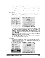
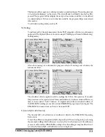
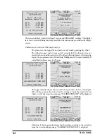
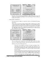
The EM61MK2A dedicates one line of the display to show GPS status. A label
DGPS
(Differential
Global Positioning System) in text mode or
D
in graphic mode indicates that GPS readings are
differentially corrected in real time Label
AGPS
(Autonomous Global Positioning System) or
A
in
graphic mode indicates lack of differential correction. On the right side of
DGPS
or
AGPS
(
D
or
A
in graphic mode) a label small square is displayed. This square should move down and up with
the frequency of GPS update rate (usually 1 second intervals). If the square is not moving for
longer period of time it means that GPS system is not working or that it is not connected to the
field computer. Number of recorded GPS positions are displayed on the right side of the small
square. This number is updated only in the logging mode, when the data are recorded. (In Stand By
mode or during Monitoring only the moving square, and updated values of PDOP and number of
tracked satellites, indicate presence of GPS input).
Two more GPS parameters are displayed on the logger screen. These are index PDOP shown by
label
P
and number of tracked satellites represented by label
S
. The index called PDOP (Position
Dilution of Precision) measures the strength of satellite coverage for a given area. PDOP is affected
by the number of satellites visible and their relative positions in the sky. The smaller the number of
PDOP the stronger the satellite coverage is. When there are more than 5 satellites widely spaced
visible, the PDOP is 4 or less. However, when there are less satellites visible, or they are unevenly
spaced in the sky, PDOP values can be 6 or higher. In most cases, the PDOP in an open sky is less
than 3, and most accuracies given for many GPS systems are given for this norm. Refer to GPS
documentation and literature for more information related to error sources of GPS positioning.
Summary of Contents for EM61MK2A
Page 2: ......

