BLIZZARD 500-900
6
532102 - Rev.B
Tr
ansla
tion of the original instruc
tions
ENGLISH
3.1 INTENDED USE
GENIUS BLIZZARD 500-900 series gear motors are designed to operate
horizontal sliding gates for residential use (including in apartment
complexes).
One gear motor must be installed for each sliding gate section. The
gate must be moved via a rack.
Installations of BLIZZARD 500-900 must be used for vehicular traffic.
To operate the gate manually, follow the instructions in § 5.5.
!
Any other use which is not expressly specified in these instructions is
prohibited and could affect the integrity of the product and/or represent
a source of danger.
3.2 LIMITATIONS OF USE
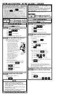
2.3 UNPACKING AND HANDLING
RISKS
PERSONAL PROTECTIVE EQUIPMENT
1. Open the package.
The gear motor casing is not fixed.
2. Remove the magnetic limit switches and the bag of accessories.
3. Remove the casing.
4. Lift the gear motor, holding it by the base.
Check that all components are present and intact
2
.
5. Dispose of the packaging materials.
After having dismantled the product, dispose of it in compliance with
the current waste disposal regulations.
Components and structural materials, batteries and electronic compo-
nents must not be disposed of together with household waste. They
must be taken to authorised disposal and recycling centres.
3. BLIZZARD 500-900
!
The packaging materials (plastic, polystyrene etc.) must not be left
within reach of children, as they are potential hazards.
When you have finished with them, dispose of the packaging in the
appropriate containers, as per applicable waste disposal regulations.
2.4 DISPOSAL OF THE PRODUCT
3.3 PROHIBITED USES
The maximum force required to move the leaf by hand over its entire
length of travel must be 225 N for residential areas and 260 N for
industrial or commercial areas.
The maximum force required to start the movement must be less
than the maximum torque at initial thrust of the operator indicated
in the technical data.
The leaf must fall within the dimensional and weight limits indicated
in the technical data.
The presence of weather conditions such as snow, ice and strong wind,
even occasional, could affect the correct operation of the automation,
the integrity of the components and be a potential source of danger
(see § Emergency use).
BLIZZARD 500-900 is not designed to be a security (break-in protec-
tion) system.
If there is a pedestrian access gate integrated in the leaf of the gate,
the motorised movement must be disabled when the pedestrian gate
is not in a safe position.
The installation must be visible during the day and at night. If it is
not, appropriate solutions must be provided to make the fixed and
moving parts visible .
The BLIZZARD 500-900 must be connected to a GENIUS electronic
board as indicated in this manual ( Technical characteristics).
Implementing the automation requires the installation of the neces-
sary safety devices, identified by the installer through an appropriate
risk assessment of the installation site.
-
Uses other than the intended use are prohibited.
-
It is prohibited to install the automation system outside of the
limits specified in the Technical Data and Installation Require-
ments sections.
-
It is forbidden to use BLIZZARD 500-900 in a constructional
configuration other than the one provided by the manufacturer.
-
No component part of the product may be modified.
-
It is prohibited to install the automation system on escape routes.
-
It is prohibited to install the automation system to create fire
doors.
-
It is prohibited to install the automation system in environments
in which there is a risk of explosion and/or fire: the presence of
flammable gases or fumes is a serious safety hazard.
-
It is prohibited to power the system with energy sources other
than those specified.
-
It is prohibited to integrate commercial systems and/or
equipment other than those specified, or use them for purposes
not intended and authorised by their respective manufacturers.
-
Do not allow water jets of any type or size to come into direct
contact with the gear motor.
-
Do not expose the gear motor to corrosive chemicals or atmo-
spheric agents.
-
It is prohibited to use and/or install accessories which have not
been specifically approved by FAAC S.p.A.
-
It is prohibited to use the automation system before performing
commissioning.
-
It is prohibited to use the automation system in the presence of
faults which could compromise safety.
-
It is prohibited to use the automation system with the fixed and/
or mobile guards removed or altered.
-
Do not use the automation system unless the area of operation
is free of persons, animals or objects.
-
Do not enter/remain in the area of operation of the automation
system while it is moving.
-
Do not try to prevent the movement of the automation system.
-
Do not climb on, hold onto or let yourself be pulled by the
leaf. Do not climb onto the gear motor.
-
Do not allow children to approach or play in the area of operation
of the automation system.
-
Do not allow the control devices to be used by anyone who is