


Part No. 75861
Genie Z-60/34
3 - 11
November 2003
Section 3 • Scheduled Maintenance Procedures
REV A
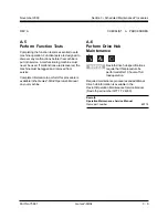
A-9
Perform 30 Day Service
The 30 day maintenance procedure is a one time
sequence of procedures to be performed after the
first 30 days or 50 hours of usage, whichever
comes first. After this interval, refer to the
maintenance tables for continued scheduled
maintenance.
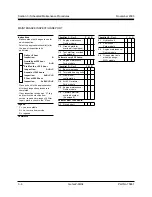
1 Perform the following maintenance procedures:
• A-10
Perform Engine Maintenance -
Ford Models
• A-13
Grease the Turntable Rotation Bearing
and Rotate Gear
• B-7
Check the Lug Nut Torque
(including tires and wheels)
• B-9
Check the Oil Level in the Drive Hubs
• B-21
Replace the Hydraulic Filters
• C-1
Perform Engine Maintenance -
Deutz Models
• D-2
Check the Turnable Rotation Bearing
Bolts
CHECKLIST
A
PROCEDURES
A-10
Perform Engine Maintenance -
Ford Models
Engine specifications require that
this procedure be performed every
100 hours. Perform this procedure
more often if dusty conditions exist
or the machine is subjected to
extended low idle operation.
Proper engine maintenance, following the engine
manufacturer's maintenance schedule, is essential
to good engine performance and service life. Failure
to perform the maintenance procedures can lead to
poor engine performance and component damage.
Required maintenance procedures and additional
engine information are available in the
Ford LRG-425 EFI Operator Handbook
(Ford part number FPP 194-302).
Ford LRG-425 EFI Operator Handbook
Genie part number
77831
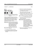
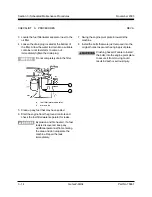
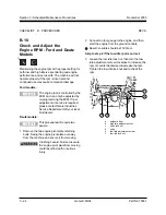
To access the engine:
1 Remove the two engine pivot plate retaining
bolts. Swing the engine pivot plate out away
from the machine and secure it from moving.
Crushing hazard. Failure to secure
the engine pivot plate from moving
could result in death or serious
injury.
Summary of Contents for Z-60/34
Page 12: ...Genie Z 60 34 Part No 75861 November 2003 This page intentionally left blank ...
Page 157: ......
Page 160: ...Electrical Schematic Deutz F4L 1011F Models November 2003 Section 6 Schematics ...
Page 162: ...Ground Control Box Wiring Diagram Deutz F4L 1011F Models November 2003 Section 6 Schematics ...
Page 164: ...Platform Control Box Wiring Diagram Deutz F4L 1011F Models November 2003 Section 6 Schematics ...
Page 165: ......
Page 168: ...Electrical Schematic Ford LRG 425 EFI Models November 2003 Section 6 Schematics ...
Page 170: ...Ground Control Box Wiring Diagram Ford LRG 425 EFI Models November 2003 Section 6 Schematics ...
Page 173: ...November2003 Section 6 Schematics PartNo 75861 GenieZ 60 34 6 11 ...
Page 176: ...Hydraulic Schematic 2WD Models before serial number 4461 November 2003 Section 6 Schematics ...
Page 178: ...Hydraulic Schematic 4WD Models before serial number 4461 November 2003 Section 6 Schematics ...
Page 180: ...Hydraulic Schematic 2WD Models after serial number 4460 November 2003 Section 6 Schematics ...
Page 182: ...Hydraulic Schematic 4WD Models after serial number 4460 November 2003 Section 6 Schematics ...


