


Part No. 75861
Genie Z-60/34
4 - 45
November 2003
Section 4 • Repair Procedures
REV A
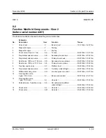
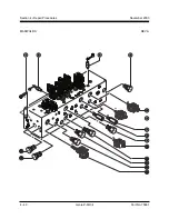
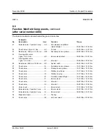
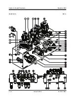
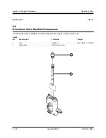
8-4
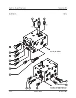
Valve Adjustments -
Function Manifold
How to Adjust the System
Relief Valve
Perform this procedure with the
boom in the stowed position.
1 Connect a 0 to 5000 psi / 0 to 345 bar pressure
gauge to the test port (item Z) on the function
manifold.
2 Start the engine from the ground controls.
3 Hold the function enable switch to the high rpm
position and activate and hold the retract switch
with the boom fully retracted.
4 Observe the pressure reading on the pressure
gauge. Refer to Section 2, Specifications.
5 Turn the engine off. Use a wrench to hold the
relief valve and remove the cap (item T).
6 Adjust the internal hex socket. Turn it clockwise
to increase the pressure or counterclockwise to
decrease the pressure. Install the relief valve
cap.
Tip-over hazard. Do not adjust
the relief valve higher than
specified.
7 Repeat steps 2 through 5 and recheck relief
valve pressure.
8 Remove the pressure gauge.
How to Adjust the Primary Boom
Down Relief Valve
Perform this procedure with the
boom in the stowed position.
1 Connect a 0 to 5000 psi / 0 to 345 bar pressure
gauge to the test port (item Z) on the function
manifold.
2 Start the engine from the ground controls.
3 Hold the function enable switch to the high rpm
position and activate and hold the primary
boom down switch with the primary boom fully
lowered.
4 Observe the pressure reading on the pressure
gauge. Refer to Section 2, Specifications.
5 Turn the engine off. Use a wrench to hold the
relief valve and remove the cap (item AE).
6 Adjust the internal hex socket. Turn it clockwise
to increase the pressure or counterclockwise to
decrease the pressure. Install the relief valve
cap.
Tip-over hazard. Do not adjust
the relief valve higher than
specified.
7 Repeat steps 2 through 5 and recheck relief
valve pressure.
8 Remove the pressure gauge.
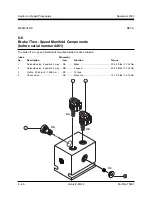
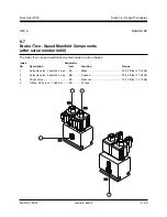
MANIFOLDS
Summary of Contents for Z-60/34
Page 12: ...Genie Z 60 34 Part No 75861 November 2003 This page intentionally left blank ...
Page 157: ......
Page 160: ...Electrical Schematic Deutz F4L 1011F Models November 2003 Section 6 Schematics ...
Page 162: ...Ground Control Box Wiring Diagram Deutz F4L 1011F Models November 2003 Section 6 Schematics ...
Page 164: ...Platform Control Box Wiring Diagram Deutz F4L 1011F Models November 2003 Section 6 Schematics ...
Page 165: ......
Page 168: ...Electrical Schematic Ford LRG 425 EFI Models November 2003 Section 6 Schematics ...
Page 170: ...Ground Control Box Wiring Diagram Ford LRG 425 EFI Models November 2003 Section 6 Schematics ...
Page 173: ...November2003 Section 6 Schematics PartNo 75861 GenieZ 60 34 6 11 ...
Page 176: ...Hydraulic Schematic 2WD Models before serial number 4461 November 2003 Section 6 Schematics ...
Page 178: ...Hydraulic Schematic 4WD Models before serial number 4461 November 2003 Section 6 Schematics ...
Page 180: ...Hydraulic Schematic 2WD Models after serial number 4460 November 2003 Section 6 Schematics ...
Page 182: ...Hydraulic Schematic 4WD Models after serial number 4460 November 2003 Section 6 Schematics ...


