background image

Section 4 • Repair Procedures

March 2015

4 - 28

GTH-1048 • GTH-1056

Part No. 123701

How to Remove the Dash Cluster
Assembly

1 Open the access door above the hydraulic tank.

2 Disconnect the battery from the machine.

Electrocution hazard. Contact with
electrically charged circuits could
result in death or serious injury.
Remove all rings, watches and
other jewelry.

3 Remove the fasteners securing the

transmission control lever to the column.
Carefully separate the lever from the column.

4 Reach under the dashboard and gently push

the dash cluster through the opening in the
dashboard.

5 Tag and disconnect the wire harness from the

dash cluster. Remove the dash cluster from the
machine.

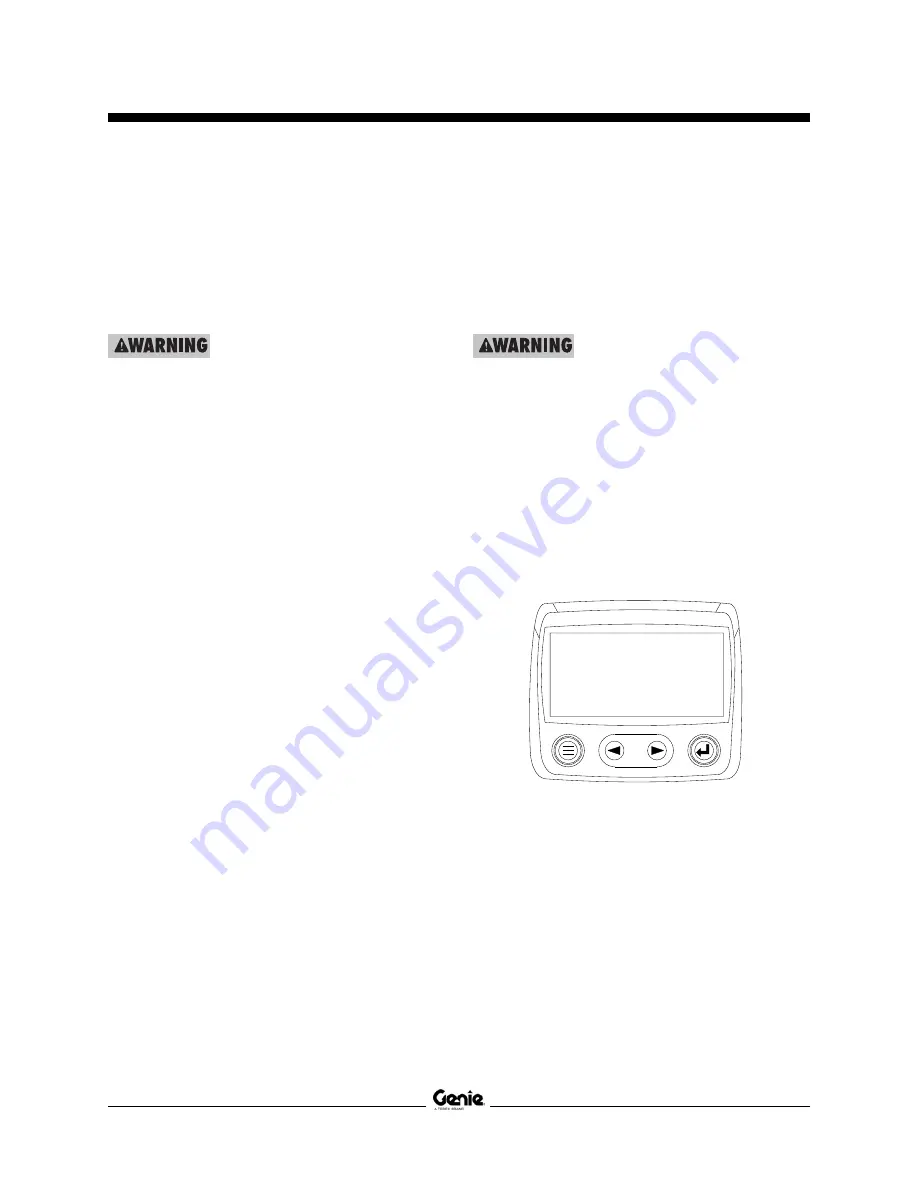
How to Remove the Diagnostic
Display

1 Open the access door above the hydraulic tank.

2 Disconnect the battery from the machine.

Electrocution hazard. Contact with
electrically charged circuits could
result in death or serious injury.
Remove all rings, watches and
other jewelry.

3 Reach under the dashboard and gently loosen

and remove the locknut securing the diagnostic
display to the dashboard. Gently push the
diagnostic display through the opening in the
dashboard.

4 Tag and disconnect the wire harness from the

diagnostic display. Remove the diagnostic
display from the machine.

OPERATOR'S COMPARTMENT

Summary of Contents for GTH-1048

Page 1: ...Parts Manual Serial Number Range Service Manual Part No 123701 Rev F2 May 2015 Serial Number Range GTH 1048 GTH 1056 from GTH1007B 7101 from GTH1007A 11697 from GTH1014E 10001 from GTH1010 14001 ...

Page 2: ...procedures require specialized skills tools lifting equipment and a suitable workshop In these instances we strongly recommend that maintenance and repair be performed at an authorized dealer service center Compliance MachineClassification Group B Type 3 as defined by ISO 16368 Machine Design Life Unrestricted with proper operation inspection and scheduledmaintenance Technical Publications Genie h...

Page 3: ...19 3 21 3 22 3 29 3 31 3 32 3 33 3 34 6 Schem 6 22 6 23 D 6 2013 5 Fault 5 8 17 5 18 19 E 8 23 2013 3 Maint 3 19 3 21 22 F 9 2014 2 Spec Hydraulic Oil 3 Maint A 6 D 7 ZF Transmission maint 2 Fault Deutz Fault Codes 6 Schem Telematics Connector Legend Electrical Schematic Harness Maps 6 3 F1 3 2015 2 Repair 4 55 Electrical Schematics Hydraulic Schematics F2 5 2015 6 Schem 6 5 6 40 ElectronicVersion...

Page 4: ...H 1048 GTH 1056 Part No 123701 REVISIONHISTORY CONTINUED Revision Date Section Procedure Schematic Page Description ElectronicVersion Click on any procedure or page number highlighted in blue to view the update iv ...

Page 5: ...1007B 7101 ATTACHMENT MANUFACTURE DATE 04 12 07 TOTAL TRUCK WEIGHT LBS 29 000lbs 13 182kg MAX LIFT CAPACITY LBS 10000 LBS LIFT CAPACITY LBS AT MAX LIFT HEIGHT OUTRIGGERS UP OUTRIGGERS DOWN N A N A 6000 LBS THIS FORKLIFT TRUCK COMPLIES WITH ASME B56 6 2002 SAFETY STD FOR ROUGH TERRAIN FORKLIFT TRUCK Serial label located inside fork frame models with quick attach frame Serial label located inside ch...

Page 6: ...May 2015 GTH 1048 GTH 1056 Part No 123701 vi This page intentionally left blank ...

Page 7: ...he hazards identified in the operator s manual are also safety hazards when maintenance and repair procedures are performed Do Not Perform Maintenance Unless You are trained and qualified to perform maintenance on this machine You read understand and obey manufacturer s instructions and safety rules employer s safety rules and worksite regulations applicable governmental regulations You have the a...

Page 8: ...her protective clothing if the situation warrants it Be aware of potential crushing hazards such as moving parts free swinging or unsecured components when lifting or placing loads Always wear approved steel toed shoes Workplace Safety Be sure to keep sparks flames and lighted tobacco away from flammable and combustible materials like battery gases and engine fuels Always have an approved fire ext...

Page 9: ...s 2 6 ManifoldComponentSpecifications 2 7 AC Refrigerant Specification 2 7 Valve Coil Resistance Specifications 2 7 JohnDeere4045TH485Engine 2 8 Deutz TCD3 6 L4 Engine 2 9 Perkins1104D E44TAEngine 2 10 Perkins1204E E44TAEngine 2 11 DanaT20000Transmission 2 12 Dana Planetary 213 Drive Axle 2 12 Hydraulic Hose and Fitting Torque Specifications 2 13 SAE and Metric Fasteners Torque Charts 2 16 Section...

Page 10: ...form Axle Maintenance 3 10 A 9 Perform Engine Maintenance John Deere Models 3 10 A 10 Perform Axle Maintenance 3 11 A 11 Perform Axle Maintenance 3 11 ChecklistBProcedures B 1 Inspect the Battery 3 12 B 2 Inspect the Electrical Wiring 3 12 B 3 Check the Exhaust System 3 13 B 4 Inspect the Engine Air Filter 3 14 B 5 Inspect the Tires Wheels and Lug Nut Torque 3 14 B 6 Perform Hydraulic Oil Analysis...

Page 11: ... D 1 Inspect the Forks 3 27 D 2 Replace the Hydraulic Tank Return Filter Element 3 27 D 3 Perform Transmission Maintenance Dana Models 3 28 D 4 Perform Axle Maintenance 3 28 D 5 Perform Engine Maintenance Deutz Models 3 29 D 6 Perform Engine Maintenance Perkins Models 3 29 D 7 Perform Transmission Maintenance ZF Models ChecklistEProcedures E 1 Test or Replace the Hydraulic Oil 3 30 E 2 Perform Eng...

Page 12: ...Boom 4 4 1 3 Boom Lift Cylinder 4 17 1 4 Boom Extension Cylinder 4 18 1 5 Fork Level Cylinder 4 19 Operator sCompartment 2 1 Operator sCompartment 4 23 2 2 MachineControls 4 25 Fuel and Hydraulic Tanks 3 1 Fuel and Hydraulic Tanks 4 29 Engines 4 1 Engines 4 30 4 2 Engine Fault Codes 4 32 Transmission 5 1 Transmission 4 33 HydraulicPumps 6 1 HydraulicPump 4 35 ...

Page 13: ...tion Manifold Components Models with Dual Joysticks 4 46 7 3 Secondary Function Manifold Components 4 50 7 4 Outrigger Manifold Components 4 52 7 5 Auxiliary Manifold Components option 4 54 7 6 Brake Manifold Components 4 55 7 7 AC Hydraulic Manifold Components 4 56 7 8 Valve Adjustments Secondary Function Manifold 4 58 7 9 Valve Coils 4 62 AxleComponents 8 1 Axles 4 64 Outriggers 9 1 Outriggers 4...

Page 14: ...5 26 Section 6 Schematics Introduction 6 1 Proximity Switch Layout 6 2 Fuse Box Layout beforeserialnumberGTH1012 16292 6 3 Fuse Box Layout fromserialnumberGTH1012 16292 6 4 Fuse Box Layout fromserialnumberGTH1014E 10353 6 5 ElectricalComponentLegend beforeserialnumberGTH1012 16292 6 6 Electrical Component Wire Color Legend fromserialnumberGTH1012 16292 6 7 TelematicsConnectorLegend 6 9 Electrical ...

Page 15: ...round 6 21 Harness Map Perkins 854E Engine Battery Power and Ground 6 24 Harness Map Options Auxiliary Hydraulics Beacon and 3rd Gear Lockout 6 25 Harness Map Options Work Lights 6 28 Harness Map Options RoadLights 6 29 Harness Map Options Enclosed Cab with Heater 6 31 Harness Map Options Enclosed Cab with HVAC 6 32 Electrical Schematic 6 35 beforeserialnumberGTH1012 16292 Electrical Schematic 6 4...

Page 16: ...May 2015 GTH 1048 GTH 1056 Part No 123701 TABLE OF CONTENTS This page intentionally left blank ...

Page 17: ...anual Tires and wheels Tire size 14 00 x 24 Tire ply rating 12 Weight rough terrain tire 315 lbs air filled 142 9 kg Weight rough terrain tire 967 35 lbs foam filled 439 16 kg Weight rock lug tire 1013 35 lbs foam filled 459 16 kg Tire pressure 50 psi models with air filled tires 3 45 bar Lug nut torque 465 ft lbs 630 Nm Lug pattern 10 x 13 189 Wheel diameter 24 in 60 1 cm Wheel width 9 in 22 9 cm...

Page 18: ...unction speeds maximum GTH 1048 Boom up 12 to 14 seconds Boom down 13 to 15 seconds Boom extend 16 to 18 seconds Boom retract 15 to 17 seconds Fork rotate 19 to 21 seconds GTH 1056 Boom up 17 to 19 seconds Boom down 23 to 25 seconds Boom extend 14 to 16 seconds Boom retract 13 to 15 seconds Fork rotate 3 to 6 seconds Continuous improvement of our products is a Genie policy Product specifications a...

Page 19: ...ional fluids Consult the Genie Service Department before use Optional fluids may not have the same hydraulic lifespan and may result in component damage Note Extended machine operation can cause the hydraulic fluid temperature to increase beyond it s maximum allowable range If the hydraulic fluid temperature consistently exceeds 200 F 90 C an optional oil cooler may be required Do not top off with...

Page 20: ... with Rando HD Premium MV Chevron 5606A hydraulic oil fluid properties ISO grade 15 Viscosity index 300 Kinematic Viscosity cSt 200 F 100 C 5 5 cSt 104 F 40 C 15 0 cSt 40 F 40 C 510 Brookfield Viscosity cP 4 F 20 C 1040 cP 22 F 30 C 3310 Flash Point 180 F 82 C Pour Point 81 F 63 C Maximum continuous operating 124 F 51 C temperature Note Use of Chevron 5606A hydraulic fluid or equivalent isrequired...

Page 21: ...our Point 49 F 45 C Maximum continuous operating 180 F 82 C temperature UCON Hydrolube HP 5046 hydraulic oil fluid properties ISO grade 46 Viscosity index 192 Kinematic Viscosity cSt 200 F 100 C 22 cSt 104 F 40 C 46 cSt 40 F 40 C 1300 Flash Point None Pour Point 81 F 63 C Maximum continuous operating 189 F 87 C temperature Continuous improvement of our products is a Genie policy Product specificat...

Page 22: ...asured at test port TS 172 bar Parking brake relief valve pressure maximum 400 psi measured at test port TPB 27 5 bar Diff lock relief valve pressure maximum 400 psi measured at test port TJ 27 5 bar Rear lock up relief valve pressure maximum 50 psi measured at test port TR 3 4 bar Outrigger Manifold Flow regulator 6 gpm Outrigger circuit 22 7 L min Continuous improvement of our products is a Geni...

Page 23: ...tic items AAC DO3 valve 3 position 4 way 5 6Ω 12V DC with diode schematic items CA and EB Solenoid valve 2 position 2 way 8 8Ω 12V DC with diode schematic items FA Solenoid valve 2 position 3 way 8 9Ω 12V DC with diode schematic items CF CO and CP Solenoid valve 2 position 4 way 7 3Ω 12V DC with diode schematic items CG Solenoid valve 3 position 4 way 7 3Ω 12V DC with diode schematic items DA and ...

Page 24: ... requirements Units ship with John Deere Engine Break In Oil During the break in period add John Deere Engine Break In Oil as needed to maintain the specified oil level Extreme operating temperatures may require the use of alternative engine oils For oil requirements refer to the Engine Operator s Manual on your machine Injection system Injection pump make Stanadyne Peak injection pressure 10 000 ...

Page 25: ...API CJ4 low emission LE oil Extreme operating temperatures may require the use of alternative engine oils For oil requirements refer to the Engine Operator s Manual on your machine Fuel requirement For fuel requirements refer to the engine Operator s Manual on your machine Fuel injection pressure maximum 23200 psi 1600 bar Enginecoolant Capacity 4 5 gallons 17 liters Type Extended Life Alternator ...

Page 26: ...he use of alternative engine oils For oil requirements refer to the Engine Operation and Maintenance Manual on your machine Injection system Injector pressure minimum 23700 psi 1634 bar Fuel requirement For fuel requirements refer to the engine Operation Manual on your machine Engine coolant Capacity 4 6 gallons 17 liters Type Extended Life Alternator Output 85 A 14V DC Fan belt tension 90 ft lb 4...

Page 27: ...ith 15W 40 API CJ4 low ash oil Extreme operating temperatures may require the use of alternative engine oils For oil requirements refer to the Engine Operation and Maintenance Manual on your machine Fuel requirement For fuel requirements refer to the engine Operation Manual on your machine Fuel Injection Pressure 23000 psi 1585 bar Enginecoolant Capacity 4 9 gallons 18 5 liters Type Extended Life ...

Page 28: ...a part number 0202 Dana 0202 Maintenance Manual Genie part number 115025 ZF 4 WG 98 TC Transmission Transmission Type 4 speed powershift converter Speeds Forward 4 Speeds Reverse 3 Torque Converter Maximum input 2600 rpm Maximum torque 480 Nm Lubrication Oil capacity 16 9 quarts 16 liters Oil viscosity requirements Units ship with Chevron Delo 400 LE SAE 15W40 Extreme operating temperatures may re...

Page 29: ...xle Lubrication Rear differential 15 quarts 14 2 liters Axle planetary end each 2 quarts 1 9 liters Oil viscosity requirements Differential Chervron Supreme 80W90 LS Planetary ends Chervron Supreme 80W90 LS For additional axle information refer to the Dana 213 Axle Maintenance and Repair Manual Dana part number 0243 Dana 213 Axle Maintenance and Repair Manual Genie part number 115026 Continuous im...

Page 30: ...4 16 1 10 7 8 14 1 12 1 1 16 12 1 16 1 5 16 12 1 20 1 5 8 12 1 24 1 7 8 12 1 SAE O ring Boss Port tube fitting installed into Aluminum all types SAE Dash size Torque 4 14 ft lbs 19 Nm 6 23 ft lbs 31 2 Nm 8 36 ft lbs 54 2 Nm 10 62 ft lbs 84 Nm 12 84 ft lbs 114 Nm 16 125 ft lbs 169 5 Nm 20 151 ft lbs 204 7 Nm 24 184 ft lbs 249 5 Nm SAE O ring Boss Port tube fitting installed into Steel SAE Dash size...

Page 31: ...se end has been tightened beyond finger tight Note The O rings used in the Parker Seal Lok fittings and hose ends are custom size O rings They are not standard SAE size O rings They are available in the O ring field service kit Genie part number49612 2 Lubricate the O ring before installation 3 Be sure that the face seal O ring is seated and retainedproperly 4 Position the tube and nut squarely on...

Page 32: ... PartNo 123701 SPECIFICATIONS 4 Tighten the hex nut until the mark on the hex nut is aligned with the second mark on the body hex fitting 5 Operate all machine functions and inspect the hoses and fittings and related components to confirm that there are no leaks ...

Page 33: ...in lbs N m in lbs N m in lbs N m in lbs N m 20 80 9 100 11 3 110 12 4 140 15 8 130 14 7 28 90 10 1 120 13 5 120 13 5 160 18 140 15 8 ft lbs N m ft lbs N m ft lbs N m ft lbs N m ft lbs N m 18 13 17 6 17 23 18 24 25 33 9 21 28 4 24 14 19 19 25 7 20 27 1 27 36 6 24 32 5 16 23 31 2 31 42 33 44 7 44 59 6 38 51 5 24 26 35 2 35 47 4 37 50 1 49 66 4 43 58 3 14 37 50 1 49 66 4 50 67 8 70 94 7 61 82 7 20 41...

Page 34: ...Section 2 Specifications September2014 2 18 GTH 1048 GTH 1056 PartNo 123701 This page intentionally left blank SPECIFICATIONS ...

Page 35: ... machine in the following configuration Machine parked on a firm level surface Boom in the stowed position Key switch in the off position with the key removed Wheels chocked About This Section This section contains detailed procedures for each scheduled maintenance inspection Each procedure includes a description safety warnings and step by step instructions Symbols Legend Safety alert symbol used...

Page 36: ...d inspection Make copies of the Pre delivery Preparation report to use for each inspection Store completed forms as required Maintenance Schedule There are five types of maintenance inspections that must be performed according to a schedule daily quarterly semi annually annually and two year The Scheduled Maintenance Procedures Section and the Maintenance Inspection Report have been divided into f...

Page 37: ...ce a check in the appropriate box after each part is completed Follow the instructions in the operator s manual If any inspection receives an N remove the machine from service repair and reinspect it After repair place a check in the R box Legend Y yes completed N no unable to complete R repaired Comments Fundamentals It is the responsibility of the dealer to perform the Pre delivery Preparation T...

Page 38: ...September2014 3 4 GTH 1048 GTH 1056 PartNo 123701 Section 3 Scheduled Maintenance Procedures This page intentionally left blank ...

Page 39: ...ce Perform every 200 hours A 11 Axle maintenance Checklist B Y N R B 1 Battery B 2 Electrical wiring B 3 Exhaust system B 4 Engine air filter B 5 Tires and wheels B 6 Hydraulic oil B 7 Tank venting systems B 8 Boom wear pads B 9 Lubricate driveshafts B 10 Engine maintenance John Deere models B 11 Engine maintenance Deutz models Checklist C Y N R C 1 Engine maintenance John Deere models C 2 Axle ma...

Page 40: ... operating conditions 1 Check to make sure that the operator s and safety manuals are present and complete in the storage container in the operator s compartment Checklist A Procedures 2 Examine the pages of each manual to be sure that they are legible and in good condition Result The operator s manual is appropriate for the machine and all manuals are legible and in good condition Result The oper...

Page 41: ...nspection also serves to determine if routine maintenance procedures are required Complete information to perform this procedure is available in the appropriate operator s manual Refer to the Operator s Manual on your machine A 3 Perform Function Tests Genie specifications require that this procedure be performed every 8 hours or daily whichever comes first Completing the function tests is essenti...

Page 42: ... Perform Engine Maintenance All Models Note Engine specifications require that this procedure be performed every 8 hours or daily whichever comes first Engine oil level check Coolant level check add Fuel system filter water separator drain Engine tightness check or leaks Exhaust system check for leaks Required maintenance procedures and additional engine information is available in the Perkins 110...

Page 43: ...tenance Manual Genie part number 115025 ZF 4 WG 98 TC Operating Manual Genie part number 1258405 CHECKLIST A PROCEDURES A 7 Perform 30 Day Service The 30 day maintenance procedure is a one time sequence of procedures to be performed after the first 30 days or 40 hours of usage After this interval refer to the maintenance checklists for continued scheduled maintenance 1 Perform the following mainte...

Page 44: ...is available in the Dana 213 Axle Maintenance and Repair Manual Danapartnumber0243 Dana 213 Axle Maintenance and Repair Manual Genie part number 115026 A 9 Perform Engine Maintenance John Deere Models Engine specifications requires that this one time procedure be performed after 100 hours of operation Required maintenance procedures and additional engine information is available in the John Deere ...

Page 45: ...n is available in the Dana 213 Axle Maintenance and Repair Manual Dana part number 0243 Dana 213 Axle Maintenance and Repair Manual Genie part number 115026 A 10 Perform Axle Maintenance Axle specifications require that this one time procedure be performed after 100 hours of operation Required maintenance procedures and additional axle information is available in the Dana 213 Axle Maintenance and ...

Page 46: ...corrosion on the battery terminals and cables 3 Be sure that the battery hold downs and cable connections are tight B 2 Inspect the Electrical Wiring Genie requires that this procedure be performed every 250 hours or quarterly whichever comes first Maintaining electrical wiring in good condition is essential to safe operation and good machine performance Failure to find and replace burnt chafed co...

Page 47: ...ne and lower the boom to the stowed position Turn the machine off B 3 Check the Exhaust System Genie requires that this procedure be performed every 250 hours or quarterly whichever comes first Maintaining the exhaust system is essential to good engine performance and service life Running the engine with a damaged or leaking exhaust system can cause component damage and unsafe operating conditions...

Page 48: ...using low pressure dry compressed air or carefully tap out dust 6 Install the secondary filter element first then install the primary filter element 7 Install the front cover onto the air cleaner assembly and secure the latches B 5 Inspect the Tires Wheels and Lug Nut Torque Genie requires that this procedure be performed every 250 hours or quarterly whichever comes first Maintaining the tires and...

Page 49: ...lysis Genie requires that this procedure be performed every 250 hours or quarterly whichever comes first Replacement or testing of the hydraulic oil is essential for good machine performance and service life Dirty oil may cause the machine to perform poorly and continued use may cause component damage Extremely dirty conditions may require oil changes to be performed more often Refer to Section 2 ...

Page 50: ...ach Note Perform this procedure with the engine off 1 Remove the cap from the fuel tank 2 Check for proper venting Result Air passes through the fuel tank cap Proceed to step 4 Result If air does not pass through the cap clean or replace the cap Proceed to step 3 Note When checking for positive tank cap venting air should pass freely through the cap 3 Using a mild solvent carefully wash the cap ve...

Page 51: ... pads is visible The wear pads are good Result All of the wear indicator of one or both wear pads is not visible Replace both wear pads Refer to Repair Procedure 1 2 How to Replace the Boom Wear Pads 5 Visually inspect both side wear pad at the pivot end of the boom Result Some of the wear indicator of both wear pads is visible The wear pads are good Result All of the wear indicator of one or both...

Page 52: ... and continued use may cause component damage 1 Using a grease gun thoroughly grease the driveshafts at each of the locations indicated in the illustration Grease Specification Chevron Ultra duty grease EP NLGI 2 lithium based or equivalent B 10 Perform Engine Maintenance John Deere Models Engine specifications require that this procedure be performed every 250 hours of operation Requiredmaintenan...

Page 53: ...m Deutz DQC II LA approved oil API CJ 4 low ash approved oil Deutz DQC III LA approved oil in extreme conditions Engines without exhaust after treatment system Deutz DQC II LA approved oil API CJ 4 low ash approved oil Deutz DQC III approved oil in extreme conditions Deutz DQC III LA approved oil in extreme conditions Required maintenance procedures and additional engine information is available i...

Page 54: ...dditional engine information is available in the John Deere 4045HF485 Operator s Manual John Deere part number OMRG36852 John Deere 4045HF485 Operator s Manual Genie part number 123703 C 2 Perform Axle Maintenance Axle specifications require that this procedure be performed after 500 hours of operation Requiredmaintenanceproceduresandadditional axle information is available in the Dana 213 Axle Ma...

Page 55: ... Maintenance Manual Dana part number 0202 Dana T20000 Maintenance Manual Genie part number 115025 C 4 Perform Engine Maintenance Deutz Models Note Engine specifications require that this procedure be performed every 500 hours Coolant additiveconcentration check Intake pipes check for damage V belts check Fuel pre filter clean change insert if necessary Requiredmaintenanceproceduresandadditional en...

Page 56: ...aintenance Manual Perkins part number SEBU8605 01 Perkins 1104 Operation and Maintenance Manual Genie part number 117765 Perkins 1204 Operation and Maintenance Manual Genie part number 218726 C 5 Perform Engine Maintenance Perkins Models Note Engine specifications require that this procedure be performed every 500 hours 1104 Engine V belts inspect adjust replace 1204 Engine Engine oil and filter c...

Page 57: ...ting to inch loads which are beyond the rated capacity of the vehicle The load cycles and environmental conditions make it impossible to predict chain life It is therefore necessary to conduct regular inspections 1 Park the machine on a firm level surface level the boom and engage the parking brake 2 Fully extend the boom 3 Inspect the chains for the following conditions Elongation BL866 chain Mea...

Page 58: ... surfaces between the pins and links Lubricant may be applied with a brush sprayed or poured on but the chain should be well flooded with lubricant and the boom should be extended and retracted to insure that the lubricant penetrates to the working surfaces All excess lubricant should be wiped away from the external surfaces Note Do not use solvents to remove excess lubricant C 8 Adjust the Boom S...

Page 59: ...hreads before the chain tension is correct the chain has stretched too far and the chain must be replaced a nut b washer c spacer d chain anchor 8 Fully retract the boom 9 Measure the gap between the washer and the spacer The gap should be between 0 125 to 0 25 inch 3 2 mm to 6 35 mm c a d b CHECKLIST C PROCEDURES C 9 Perform Axle Maintenance Axle specifications require that this procedure be perf...

Page 60: ...rm Axle Maintenance Axle specifications require that this procedure be performed every 800 hours of operation Required maintenance procedures and additional axle information is available in the Dana 213 Axle Maintenance and Repair Manual Dana part number 0243 Dana 213 Axle Maintenance and Repair Manual Genie part number 115026 ...

Page 61: ...ve and properly discard the filter element Note To reduce the amount of oil spilled it may be helpful to drain the element into the tank during replacement 6 Install the new filter element Install and securely tighten the cap 7 Clean up any oil that may have spilled a b D 1 Inspect the Forks Genie specifications require that this procedure be performed every 1000 hours or annually whichever comes ...

Page 62: ...ansmission information is available in the Dana T20000 Maintenance Manual Dana part number 0202 Dana T20000 Maintenance Manual Genie part number 115025 D 4 Perform Axle Maintenance Axle specifications require that this procedure be performed every 1000 hours of operation Required maintenance procedures and additional axle information is available in the Dana 213 Axle Maintenance and Repair Manual ...

Page 63: ...ation is available in the Deutz TCD3 6 Operation Manual Deutz part number 0312 3907 Deutz TCD3 6 Operation Manual Genie part number 218707 D 6 Perform Engine Maintenance Perkins Models Note Engine specifications require that this procedure be performed every 1000 hours 1104 Engine Engine valve lash inspect adjust 1204 Engine Water pump inspect Required maintenance procedures and additional engine ...

Page 64: ...nsmission specifications require that this procedure be performed every 1500 hours Transmission oil and filter change Requiredmaintenanceproceduresandadditional transmission information is available in the ZF 4 WG 98 TC Maintenance Manual ZF part number 5872 134 002 ZF 4 WG 98 TC Operating Manual Genie part number 1258405 CHECKLIST D PROCEDURES ...

Page 65: ...lic system Note Before replacing the hydraulic oil the oil may be tested by an oil distributor for specific levels of contamination to verify that changing the oil is necessary If the hydraulic oil is not replaced at the two year inspection test the oil quarterly Replace the oil when it fails the test 1 Lower the boom to the stowed position 2 Remove the filler cap from the hydraulic tank 3 Place a...

Page 66: ... Perkins Models Note Engine specifications require that this procedure be performed every 2000 hours 1104 Engine Aftercooler core inspect Alternator inspect Engine mounts inspect Starting Motor inspect Turbocharger inspect Water pump inspect 1204 Engine Aftercooler core inspect Engine mounts inspect Starting motor inspect Turbocharger inspect Required maintenance procedures and additional engine i...

Page 67: ...lable in the Perkins 1104 Operation and Maintenance Manual Perkins part number SEBU7833 01 OR the Perkins 1204 Operation and Maintenance Manual Perkins part number SEBU8605 01 Perkins 1104 Operation and Maintenance Manual Genie part number 117765 Perkins 1204 Operation and Maintenance Manual Genie part number 218726 E 4 Perform Engine Maintenance Deutz Models Note Engine specifications require tha...

Page 68: ... is available in the Perkins 1204 Operation and Maintenance Manual Perkins part number SEBU8605 01 Perkins 1204 Operation and Maintenance Manual Genie part number 218726 E 7 Perform Engine Maintenance John Deere Models Engine specifications require that this procedure be performed every 4500 hours or 60 months whichever comes first Required maintenance procedures and additional engine information ...

Page 69: ...orm Engine Maintenance Perkins Models Note Engine specifications require that this procedure be performed every 12 000 hours or every three years whichever comes first 1104 and 1204 Engines Cooling System Coolant Extended life coolant change Required maintenance procedures and additional engine information is available in the Perkins 1104 Operation and Maintenance Manual Perkins part number SEBU78...

Page 70: ...dous situation which if not avoided may result in property damage Note Used to indicate additional operation or procedure information Indicates that a specific result is expected after performing a series of steps Indicates that an incorrect result has occurred after performing a series of steps Observe and Obey Repair procedures shall be completed by a person trained and qualified on the repair o...

Page 71: ...e of a fail safe design Should the switch or the switch wire circuit be faulty the machine will not function outside its designed range of use The boom proximity switches are components of the drive circuit and the chassis sway circuit Both the drive and the chassis sway functions are disabled when the boom is raised to 60 or higher and the boom is extended to greater than 43 feet 13 1 m Boom Comp...

Page 72: ...ity switch assembly until the light of the proximity switch just turns off 5 Securely tighten the fasteners Do not over tighten 6 Lower the machine to 55 Result The light of the proximity switch assembly is illuminated 7 Raise the boom to 60 Confirm with a digital level Result The light of the proximity switch assembly is not illuminated The proximity switch is properly calibrated Result The light...

Page 73: ...ide wear pads 4 Install the wear pads Install and securely tighten the fasteners Do not over tighten How to Remove the Lifting Fork Frame 1 With the boom in the stowed position attach a lifting strap from an overhead crane to the top of the lifting fork frame at the front of the boom Support the frame Do not apply any lifting pressure 2 Working from the rear of the frame lift the spring assisted h...

Page 74: ...e pivot end of the boom remove the fasteners securing the hose roller assembly to boom tube number 1 Remove the hose roller assembly from the boom 5 Working at the fork end of the boom remove the fasteners securing the cable track mount bracket to boom tube number 3 6 Working at the fork end of the boom remove the fasteners securing the cable bridge slider to the cable bridge Remove the slider fro...

Page 75: ...ation 1 7 GTH 1056 Working at the fork end of the boom loosen evenly the fasteners securing the single chain tensioners to the top of boom tube number 0 After noting the orientation and assembly order of the components remove the fasteners and pull the tensioners free of the boom Refer to Illustration 1 8 GTH 1048 Working at the fork end of the boom loosen the fasteners securing the single chain t...

Page 76: ...ot pin Lower the cylinder just enough for access to the chain anchor bolts 15 Working at the fork end of the boom securely connect a 30 foot 10 m length of rope to the end of the chain Securely tie off the other end of the rope to the boom structure 16 Working at the pivot end of the boom pull the chain out of the boom Note Rope coming loose from the chain during removal may result in a difficult ...

Page 77: ...be number 1 Install the mounting components removed in step 8 Evenly tighten the chain tensioners to the top of the boom tube until they are securely tightened 26 Adjust the chains Refer to Maintenance Procedure D 2 Adjust the Boom Sequencing Chains Component damage hazard Chains can be damaged if the boom is used while the chains are out of adjustment Do not return the machine to use until the ch...

Page 78: ...other chains 10 Working at the fork end of the boom select a chain Securely connect a 30 foot 10 m length of rope to the end of the chain Securely tie off the other end of the rope to the boom structure 11 GTH 1056 Remove the inspection cover from the pivot end of the boom and locate the chain anchors of the extension chains at the top of boom tubes 2 and 3 GTH 1048 Remove the inspection cover fro...

Page 79: ...step 8 onto the boom Install and securely tighten the fasteners Do not over tighten 22 GTH 1056 Working at the fork end of boom tube number 1 install the dual chain tensioner into the tensioner mount Install the mounting components removed in step 5 and securely tighten the fasteners 23 GTH 1056 Install the chain tensioners into the tensioner mount at the fork end of boom tube number 0 Install the...

Page 80: ...lowering the cylinder 7 Repeat this procedure beginning with step 3 for the other fork level cylinder 8 Select a lift cylinder Tag disconnect and plug the hydraulic hoses at the lift cylinder manifold Cap the fittings on the cylinder manifold 9 Remove the fasteners securing the lift cylinder barrel end pivot pin to the chassis 10 Support and secure the barrel end of the lift cylinder to the boom 1...

Page 81: ... and fall if not properly supported when removed from the machine 6 Repeat this procedure beginning with step 3 for the other lift cylinder 7 Remove the fastener securing the fork level cylinder rod end pivot pin to the fork frame mount 8 Use a soft metal drift to remove the rod end pivot pin 9 Attach a lifting strap from an overhead crane to the barrel end of the fork level cylinder Support the c...

Page 82: ...e retraction chain block pivot pin to boom tube number 3 Remove the pivot pin Remove the chain from the roller 22 Working at the pivot end of the boom remove the fasteners securing the retraction chain roller to boom tube number 2 Remove the chain roller from the boom 23 Working at the fork end of the boom remove the wear pads from boom tube number 2 24 Support and slide boom tube number 3 out of ...

Page 83: ...perly supported when removed from the machine 6 Repeat this procedure beginning with step 3 for the other lift cylinder 7 Remove the fastener securing the fork level cylinder rod end pivot pin to the fork frame mount 8 Use a soft metal drift to remove the rod end pivot pin 9 Attach a lifting strap from an overhead crane to the barrel end of the fork level cylinder Support the cylinder Do not apply...

Page 84: ...COMPONENTS b f e d c a a cable bridge mount bracket b cable track mount bracket c cable bridge slider 19 Working at the fork end of the boom remove the fasteners securing the cable bridge slider to the cable bridge Remove the slider from the boom Note Pay attention to how the hoses are routed before removing the slider from the boom Note During reassembly it may be helpful to use tape to secure th...

Page 85: ...vot pin to boom tube number 2 Remove the pivot pin 30 Working at the pivot end of the boom remove the fasteners securing the chain roller to boom tube number 2 Remove the chain roller from the boom BOOM COMPONENTS 31 Working at the fork end of the boom remove the wear pads from boom tube number 1 32 Support and slide boom tube number 2 out of boom tube number 1 Place boom tube number 2 on a struct...

Page 86: ...ery slowly to allow the oil pressure to dissipate gradually Do not allow oil to squirt or spray Component damage hazard Hoses can be damaged if they are kinked or pinched 3 Attach a lifting strap from an overhead crane to the rod end of the lift cylinder Support the cylinder Do not apply any lifting pressure 4 Remove the fasteners securing the lift cylinder barrel end pivot pin to the chassis 5 Us...

Page 87: ...oil pressure to dissipate gradually Do not allow oil to squirt or spray Component damage hazard Hoses can be damaged if they are kinked or pinched 3 Attach a lifting strap from an overhead crane to the center point of the boom extension cylinder Support the cylinder Do not apply any lifting pressure 4 Remove the extension cylinder support loop from the underside of the boom Note The extension cyli...

Page 88: ... strap from an overhead crane to the barrel end of the fork level cylinder Support the cylinder Do not apply any lifting pressure 5 Tag disconnect and plug the fork level cylinder hoses from the cylinder manifolds Cap the fittings Bodily injury hazard Spraying hydraulic oil can penetrate and burn skin Loosen hydraulic connections very slowly to allow the oil pressure to dissipate gradually Do not ...

Page 89: ... from the hydraulic hard lines under boom tube number number 1 Cap the hard lines 7 Securely connect a 30 feet 10 m length of rope to each end of the hoses disconnected in steps 5 and 6 Securely tie off the other end of each section of rope to the boom structure 8 Working at the pivot end of the boom select one of the hoses Pull the hose out of the boom Note Rope coming loose from either end of th...

Page 90: ...lic hoses from the hydraulic hard lines under boom tube number number 1 Cap the hard lines 8 Securely connect a 30 feet 10 m length of rope to the end of each hose disconnected in steps 6 and 7 Securely tie off the other end of each section of rope to the boom structure 9 Working at the pivot end of the boom select one of the hoses Pull the hose out of the boom Note Rope coming loose from either e...

Page 91: ...ng at the fork end of the boom remove the fasteners securing the cable bridge slider to the cable bridge Remove the slider from the boom Note Pay attention to how the hoses are routed before removing the slider from the boom Note During reassembly it may be helpful to use tape to secure the bolts to the cable bridge when installing the cable bridge slider 11 Remove the fasteners securing the cable...

Page 92: ...nd plug the hydraulic hoses at ports BP and BT of the secondary function manifold Cap the fittings See 7 3 Secondary Function Manifold Components 4 Locate the brake manifold under the manifold inspection cover Tag disconnect and plug the hydraulic hose at the underside of the brake manifold Cap the fitting See 7 6 Brake Manifold Components 5 Working under the dashboard locate the hydraulic hose at...

Page 93: ...ee fitting below the hydraulic oil level in the hydraulic tank will result in excessive hydraulic fluid leaking from the hose Do not disconnect the hose from the tee fitting if the tee fitting is below the hydraulic oil level in the hydraulic tank 16 Working inside the chassis tag and disconnect the wire harnesses at the connectors next to the operator s compartment 17 Support and secure the opera...

Page 94: ...f the dash panel Remove the dash panel from the machine 8 Loosen the two lower fasteners securing the dash frame to the operator s compartment 9 Remove the two upper fasteners securing the dash frame to the operator s compartment 10 Rotate the dash frame towards the seat of the operator s compartment Remove the dashboard from the machine 11 Tag and disconnect the ground wire of the steer column 12...

Page 95: ...from the machine 5 Tag disconnect and plug the hoses from ports 1 2 3 4 P and T of the joystick Cap the fittings Note Removing the hydraulic hose from port T of the joystick with the joystick below the hydraulic oil level in the hydraulic tank will result in excessive hydraulic fluid leaking from the hose Do not disconnect the hose from the port if the joystick is below the hydraulic oil level in ...

Page 96: ...low the hydraulic oil level in the hydraulic tank 8 Remove the fasteners securing the joystick to the mount panel Remove the joystick How to Remove the Brake Pedal Assembly 1 Open the access door above the hydraulic tank 2 Disconnect the battery from the machine Electrocution hazard Contact with electrically charged circuits could result in death or serious injury Remove all rings watches and othe...

Page 97: ...through the opening in the dashboard 5 Tag and disconnect the wire harness from the dash cluster Remove the dash cluster from the machine How to Remove the Diagnostic Display 1 Open the access door above the hydraulic tank 2 Disconnect the battery from the machine Electrocution hazard Contact with electrically charged circuits could result in death or serious injury Remove all rings watches and ot...

Page 98: ...m the hydraulic tank 6 Place a drain pan or other suitable container under the hydraulic tank Refer to Section 2 Specifications 7 Remove the drain plug from the hydraulic tank and completely drain the tank Bodily injury hazard Beware of hot oil Contact with hot oil may cause severe burns 8 Remove the filler cap from the fuel tank 9 Using an approved hand operated pump drain the fuel tank into a co...

Page 99: ...l Genie part number 108503 How to Repair the Perkins 1104D E44TA Engine Repairproceduresandadditionalengineinformation is available in the Perkins 1100 Operation and Maintenance Manual Perkins part number SEBU8172 00 and the Perkins 1104 Service Manual Perkins part number RENR9401 and the Perkins 1100 Troubleshooting Manual Perkins part number SENR9982 01 Perkins 1100 Operation and Maintenance Man...

Page 100: ... the fitting 8 John Deere models Open the engine access cover at the tank side of the machine Locate the fuel supply line where it is attached to the fuelfilter waterseparator 9 John Deere models Tag disconnect and plug the fuel supply hose at the fuel filter water separator Cap the fitting 10 John Deere models Open the engine access cover at the operator s compartment side of the machine Locate t...

Page 101: ... a colored warning lamp is illuminated and the fault code is shown on the engine diagnostic display is located on the dashboard in the operator s compartment To learn the specifics of and how to use the fault codes refer to Section 5 Fault Codes John Deere 4045HF485 engine a coolant temperature sender b oil pressure sender c starter relay ENGINES a b c Perkins 1104D E44TA engine a oil pressure sen...

Page 102: ...ll rings watches and other jewelry 3 Place a drain pan or other suitable container under the hydraulic tank Refer to Section 2 Specifications 4 Remove the drain plug from the hydraulic tank and completely drain the tank Bodily injury hazard Beware of hot oil Contact with hot oil may cause severe burns 5 Tag disconnect and plug the transmission oil cooler lines at the cooler Cap the fittings Bodily...

Page 103: ...plug the hydraulic pump supply line at the pump Cap the orifice on the pump 8 Remove the fasteners securing the transmission mounting flange to the chassis 9 Tag and disconnect the driveshafts from the transmission Note To avoid damage to the driveshaft universal joints secure the driveshafts to the chassis 10 Tag and disconnect the wiring harness from the transmission 11 Attach a lifting strap fr...

Page 104: ...3 Hold the manual fuel shut off lever on the engine in the closed position 4 Observe the pressure gauge while cranking the engine in one second intervals Result If the pressure gauge reads 3190 psi 220 bar immediately stop The pump is good Result If the pressure fails to reach 3190 psi 220 bar the pump needs to be adjusted OR or the pump or pump coupling is faulty and will need to be serviced or r...

Page 105: ...ap the fitting on the pump Note Placing the open end of the case drain hose below the hydraulic oil level in the hydraulic tank will result in excessive hydraulic fluid leaking from the hose Do not lower the open end of the case drain hose to below the fluid level of the hydraulic tank until the hose is plugged 5 Tag disconnect and plug the large hydraulic pump supply hose at the pump Cap the fitt...

Page 106: ...teners to 55 66 ft lbs 74 90 Nm 5 Working at the case drain at the top of the pump fill the pump with hydraulic fluid until the fluid is at the top of the case drain fitting 6 Install the case drain hose onto the pump and torque to specification Refer to Section 2 Specifications 7 Securely install the wire harness onto the pump 8 Check the level of the hydraulic fluid in the hydraulic tank Add flu...

Page 107: ...cifications 2 Locate the case drain filler plug at the side of the function pump 3 Remove the plug and slowly fill the case drain port of the pump with hydraulic fluid until the oil level is even with the bottom of the hole Install the plug and torque to 40 ft lbs 54 Nm 4 Start the engine allow the engine to run at low idle for 15 seconds then shut off the engine Wait 15 seconds then start the eng...

Page 108: ...d to step 6 Result The pressure gauge fails to read 450 25 psi 31 1 7 bar The pressure setting needs to be adjusted Proceed to step 4 4 Loosen the set screw for the standby pressure adjustment screw 5 Adjust the function pump standby pressure Turn the adjustment screw clockwise to increase the pressure or counterclockwise to decrease the pressure Tighten the set screw 6 Turn the engine off and rem...

Page 109: ...tioning correctly Proceed to step 7 Result The pressure gauge fails to read 3190 50 psi 220 3 4 bar The pressure setting needs to be adjusted Proceed to step 5 5 Loosen the set screw for the pressure compensator adjustment screw 6 Adjust the pressure compensator pressure Turn the adjustment screw clockwise to increase the pressure or counterclockwise to decrease the pressure Tighten the set screw ...

Page 110: ...Section 4 Repair Procedures March2015 PartNo 123701 GTH 1048 GTH 1056 4 41 This page intentionally left blank ...

Page 111: ...0 ft lbs 27 Nm 5 Directional valve 3 position 4 way pilot operated AE Fork tilt up down 46 54 ft lbs 61 72 Nm 6 Relief valve 3500 psi 241 bar AF Fork tilt up relief 20 ft lbs 27 Nm 7 Check valve pilot operated 100 psi 6 9 bar AG Fork tilt down circuit 25 ft lbs 34 Nm 8 Check valve pilot operated 100 psi 6 9 bar AH Fork tilt up circuit 25 ft lbs 34 Nm 9 Relief valve 3500 psi 241 bar AI Fork tilt do...

Page 112: ... AC AD AE AF AG AH 27 26 28 4 7 8 1 AI AJ AY AAA AAB AAC AP AQ AR AS AT AU AV Y82 Y71 Y70 Y72B Y72A 25 View A View A Note alpha callouts refer to corresponding notes on the hydraulic schematic alphanumeric callouts refer to the electrical schematic 24 23 AK AL AM AN AO AW AX Y71 Y70 Y82 Y72B Y72A View B View B 11 12 13 14 15 ...

Page 113: ...ilt down circuit 12 14 ft lbs 16 19 Nm 21 Check valve 5 psi 0 3 bar AU Boom up circuit 12 14 ft lbs 16 19 Nm 22 Check valve 5 psi 0 3 bar AV Boom retract circuit 12 14 ft lbs 16 19 Nm 23 Directional valve 3 position 4 way pilot operated AW Sway left right 33 37 ft lbs 45 50 Nm 24 Flow regulator valve 14 gpm 53 L min AX Fork tilt up down circuit 20 ft lbs 27 Nm 25 Solenoid valve 2 position 4 way AY...

Page 114: ... AC AD AE AF AG AH 27 26 28 4 7 8 1 AI AJ AY AAA AAB AAC AP AQ AR AS AT AU AV Y82 Y71 Y70 Y72B Y72A 25 View A View A Note alpha callouts refer to corresponding notes on the hydraulic schematic alphanumeric callouts refer to the electrical schematic 24 23 AK AL AM AN AO AW AX Y71 Y70 Y82 Y72B Y72A View B View B 11 12 13 14 15 ...

Page 115: ...4 ft lbs 61 72 Nm 5 Relief valve 3500 psi 241 bar BE Fork tilt up relief 20 ft lbs 27 Nm 6 Check valve pilot operated 100 psi 6 9 bar BF Fork tilt down circuit 25 ft lbs 34 Nm 7 Check valve pilot operated 100 psi 6 9 bar BG Fork tilt up circuit 25 ft lbs 34 Nm 8 Relief valve 3500 psi 241 bar BH Fork tilt down relief 20 ft lbs 27 Nm 9 Relief valve 3500 psi 241 bar BI System relief 25 ft lbs 34 Nm 1...

Page 116: ... 19 23 22 2 3 1 6 7 26 BA BB BC BD BE BF BG BH BI BX BAA BQ BR BS BT BU BV BW Y82 Note alpha callouts refer to corresponding notes on the hydraulic schematic alphanumeric callouts refer to the electrical schematic 8 25 BZ 24 View A View A 17 20 BJ BK BL BM BN BO BP View B View B 10 11 12 13 14 15 16 ...

Page 117: ...5 psi 0 3 bar BS Fork tilt down circuit 12 14 ft lbs 16 19 Nm 20 Check valve 5 psi 0 3 bar BT Steer left right circuit 12 14 ft lbs 16 19 Nm 21 Check valve 5 psi 0 3 bar BU Fork tilt up circuit 12 14 ft lbs 16 19 Nm 22 Check valve 5 psi 0 3 bar BV Boom up circuit 12 14 ft lbs 16 19 Nm 23 Check valve 5 psi 0 3 bar BW Boom retract circuit 12 14 ft lbs 16 19 Nm 24 Directional valve 2 position 2 way p...

Page 118: ... 19 23 22 2 3 1 6 7 26 BA BB BC BD BE BF BG BH BI BX BAA BQ BR BS BT BU BV BW Y82 Note alpha callouts refer to corresponding notes on the hydraulic schematic alphanumeric callouts refer to the electrical schematic 8 25 BZ 24 View A View A 17 20 BJ BK BL BM BN BO BP View B View B 10 11 12 13 14 15 16 ...

Page 119: ...e select 20 ft lbs 27 Nm 7 Solenoid valve 2 position 4 way CG Rear axle fast oscillate select 25 ft lbs 34 Nm 8 Check valve 4 psi 0 3 bar CH Rear lock up extend circuit 20 ft lbs 27 Nm 9 Check valve 25 psi 1 7 bar CI Drive brake circuit 20 ft lbs 27 Nm 10 Pressure switch 350 psi 24 bar PS7 Low brake pressure 11 ft lbs 14 9 Nm 11 Pressure switch 250 psi 17 2 bar PS6 Parking brake pressure 11 ft lbs...

Page 120: ...CA CB CC CD CE CF CO CP CQ CR CS 19 20 21 18 17 7 13 CG CH C I PS6 10 PS7 8 9 15 16 14 CN CM CL CK CJ 11 Y78 Y79 Y83 Y78 Y79 Y68 Y55 Y67 Note alpha callouts refer to corresponding notes on the hydraulic schematic alphanumeric callouts refer to the electrical schematic View A View A View B View B 12 ...

Page 121: ...ght outrigger extend retract 25 ft lbs 34 Nm 3 Flow regulator valve 6 gpm 22 7 L min DC Right outrigger circuit 25 ft lbs 34 Nm 4 Flow regulator valve 6 gpm 22 7 L min DD Left outrigger circuit 25 ft lbs 34 Nm 5 Check valve 5 psi 0 3 bar DE Left outrigger extend circuit 12 14 ft lbs 16 19 Nm 6 Check valve 5 psi 0 3 bar DF Right outrigger extend circuit 12 14 ft lbs 16 19 Nm 7 Check valve 5 psi 0 3...

Page 122: ...1056 4 53 MANIFOLDS 3 5 6 7 8 2 1 4 Note alpha callouts refer to corresponding notes on the hydraulic schematic alphanumeric callouts refer to the electrical schematic DA DB DC Y75 Y76 DD DE DF DG DH Y75 Y76 Y74 Y73 View A View A View B View B Y74 Y73 LSR RSR LSE RSE ...

Page 123: ...e 1 Check valve 5 psi 0 3 bar EA Auxiliary A1 circuit 12 14 ft lbs 16 19 Nm 2 DO3 valve 3 position 4 way EB Auxiliary function enable 60 in lbs 6 8 Nm 3 Flow regulator valve EC Function speed control 25 ft lbs 34 Nm 4 Check valve 5 psi 0 3 bar ED Auxiliary A2 circuit 12 14 ft lbs 16 19 Nm 2 4 3 1 EA EB EC ED Y77A Y77B Note alpha callouts refer to corresponding notes on the hydraulic schematic alph...

Page 124: ...n cover Index Schematic No Description Item Function Torque 1 Pressure switch 450 psi 31 bar PS4 Clutch cut off pressure 11 ft lbs 14 9 Nm 2 Pressure switch 50 psi 3 4 bar PS5 Brake light pressure option 11 ft lbs 14 9 Nm TO FRONT AXLE TO BRAKE PEDAL 1 2 S6 S16 Note alphanumeric callouts refer to corresponding notes on th e electrical and hydraulic schematics TO REAR AXLE ...

Page 125: ...located under the manifold inspection cover Index Schematic No Description Item Function Torque 1 Solenoid valve 2 position 2 way FA Controls motor 20 ft lbs 27 1 Nm 2 Flow control valve 3 gpm 11 3 lpm FB Regulates flow 33 37 ft lbs 45 50 Nm 1 2 FA FB Note alphanumeric callouts refer to corresponding notes on the electrical and hydraulic schematics Y84 ...

Page 126: ...Section 4 Repair Procedures March2015 PartNo 123701 GTH 1048 GTH 1056 4 57 MANIFOLDS This page intentionally left blank ...

Page 127: ...oil to squirt or spray 5 Install a 0 to 3500 psi 0 to 250 bar pressure gauge into test port TS at the top of the secondary function manifold schematic item CR See 7 3 Secondary Function Manifold Components 6 Start the engine Allow the engine to idle 7 Fully turn and hold the steering wheel in the left direction and allow the wheels to fully turn to the left Continue holding the steering while obse...

Page 128: ...y to allow the oil pressure to dissipate gradually Do not allow oil to squirt or spray MANIFOLDS 5 Install a 0 to 1000 psi 0 to 100 bar pressure gauge into test port TPB at the top of the secondary function manifold schematic item CN See 7 3 Secondary Function Manifold Components 6 Start the engine Allow the engine to idle Result The pressure gauge reads 400 psi 27 5 bar The pressure setting is co...

Page 129: ... very slowly to allow the oil pressure to dissipate gradually Do not allow oil to squirt or spray 5 Install a 0 to 1000 psi 0 to 100 bar pressure gauge into test port TJ at the top of the secondary function manifold schematic item CQ See 7 3 Secondary Function Manifold Components 6 Start the engine Allow the engine to idle Result The pressure gauge reads 400 psi 27 5 bar The pressure setting is co...

Page 130: ...azard Spraying hydraulic oil can penetrate and burn skin Loosen hydraulic connections very slowly to allow the oil pressure to dissipate gradually Do not allow oil to squirt or spray How to Set the Rear Lock up System Pressure Note Be sure that the hydraulic oil level is visible in the inspection glass of the hydraulic tank 1 Install a 0 to 1000 psi 0 to 100 bar pressure gauge into test port TP at...

Page 131: ...orming this test 1 Tag and disconnect the wiring from the coil to be tested 2 Test the coil resistance using a multimeter set to resistance Ω Refer to the Valve Coil Resistance Specification table Result If the resistance is not within the adjusted specification plus or minus 10 replace the coil Valve Coil Resistance Specification Note The following coil resistance specifications are at an ambient...

Page 132: ...e The battery should read 9V DC or more when measured across the terminals Resistor 10Ω Ω Ω Ω Ω Genie part number 27287 3 Set a multimeter to read DC amperage Note The multimeter when set to read DC amperage should be capable of reading up to 800 mA 4 Connect the negative lead to the other terminal on the coil Note If testing a single terminal coil connect the negative lead to the internal metalli...

Page 133: ...chine until the tires are off the ground Place blocks under the chassis for support Crushing hazard The chassis will fall if not properly supported 6 Remove the lug nuts Remove the tire and wheel assembly from both ends of the axle 7 Support and secure the axle to an appropriate lifting device 8 Remove the fasteners securing the sway cylinder rod end pivot pin to the chassis 9 Use a soft metal dri...

Page 134: ...e barrel end of the fork level cylinder Support the cylinder Do not apply any lifting pressure 4 Remove the fasteners securing the outrigger cylinder barrel end pivot pin to the machine 5 Use a soft metal drift to remove the outrigger cylinder barrel end pivot pin Lower the cylinder onto the outrigger Crushing hazard The cylinder may become unbalanced and fall if not properly supported when the pi...

Page 135: ...l pressure to dissipate gradually Do not allow oil to squirt or spray Component damage hazard Hoses can be damaged if they are kinked or pinched 3 Attach a lifting strap from an overhead crane to the barrel end of the outrigger cylinder Support the cylinder Do not apply any lifting pressure 4 Remove the fasteners securing the outrigger cylinder barrel end pivot pin to the chassis 5 Use a soft meta...

Page 136: ...esult in death or serious injury Remove all rings watches and other jewelry Bodily injury hazard Spraying hydraulic oil can penetrate and burn skin Loosen hydraulic connections very slowly to allow the oil pressure to dissipate gradually Do not allow oil to squirt or spray Observe and Obey Troubleshooting and repair procedures shall be completed by a person trained and qualified on the repair of t...

Page 137: ...e The ECM will in some cases automatically shut down the engine when the red light is displayed AccesstheActiveFaultCodes Componentdamagehazard Ignoring active fault codes may result in engine damage 1 Duringnormaloperation engineparametersare visible in the diagnostic display When an engine fault is detected the engine parameters on display are immediately replaced with a WARNING message Also on ...

Page 138: ...een corrected are displayed at the moment the fault is detected Stored fault codes are the cumulative history of fault codes which the ECM has detected These fault codes may be recalled by service personnel at a later time even if the condition which caused the engine fault has ceased to exist Note Additional hardware will be necessary to access stored codes on machines from serial numberGTH1012 1...

Page 139: ...ature Input Voltage Out of Range High Exhaust Gas Recirculation Air Temperature Input Voltage Out of Range Low Exhaust Gas Recirculation Air Temperature High LeastSevere Exhaust Gas Recirculation Air Temperature High Moderately Severe Barometric Air Pressure Sensor Signal Invalid Barometric Air Pressure Sensor Signal Invalid Engine Coolant Temperature High Most Severe Engine Coolant Temperature In...

Page 140: ... Current High or Grounded Circuit Engine Position Sensor Input Missing Engine Position Sensor Pattern Error Timing Crank Position Sensor Noise Timing Crank Position Sensor Current Low or Open Circuit Timing Crank Position Sensor Current High or Grounded Circuit Crank Camshaft Position Out of Sync Crank Position Input Missing Crank Position Input Pattern Error External Engine Protection Signal Not ...

Page 141: ...ine Shutdown Signal Auxiliary Engine Derate Signal Sensor Supply Voltage 3 Out of Range High Sensor Supply Voltage 3 Out of Range Low Fuel Rail Pressure Sensor Supply Voltage 2 Out of Range High Fuel Rail Pressure Sensor Supply Voltage 2 Out of Range Low Engine Protection System Approaching Shutdown Engine Protection System Shutdown Engine ECU Temperature High Most Severe ECU Temperature High Mode...

Page 142: ...age Range High Exhaust Gas Recirculation Valve Sensor Voltage Range Low Exhaust Gas Recirculation Valve Current Low or Circuit Exhaust Gas Recirculation Valve Current High or Grounded Circuit Exhaust Gas Recirculation Valve Not Responding or of Adjustment Exhaust Gas Recirculation Valve Out of Calibration Exhaust Gas Recirculation Valve Off Exhaust Gas Recirculation Valve Position Error Turbocharg...

Page 143: ...low for accelerator pedal sensor 8 PWM signal accelerator pedal out of target range to high 11 Plausibility check between APP1 and APP2 or APP1 and idle switch 94 1 Low fuel pressure is out of target range system reaction generated 3 Target range to high for low fuel pressure sensor 4 Target range to low for low fuel pressure sensor 97 3 Water in Fuel Sensor Short Circuit to U Batt 12 Water level ...

Page 144: ...Physical Range Check low for Oil Temperature 2 Oil temperature value is not plausible 3 Target range to high for oil temperature sensor 4 Target range to low for oil temperature sensor 190 0 Engine speed target range exceeded FOC range 1 2 Speed sensor of crankshaft and camshaft signals are out of phase 8 Speed sensor signal not plausible 11 Engine speed target range exceeded FOC range 2 12 Speed ...

Page 145: ... 3 5 Interruption of electric connection injector 3 654 3 General short circuit injector 4 5 Interruption of electric connection injector 4 655 3 General short circuit injector 5 5 Interruption of electric connection injector 5 656 3 General short circuit injector 6 5 Interruption of electric connection injector 6 677 3 Short circuit on high side starter relay 4 Short circuit on low side starter r...

Page 146: ... range 3241 1 Target range to low for SCR catalyst upstream temperature sensor 3251 0 Differential pressure sensor value DPF out of target range to high 1 Differential pressure sensor value DPF out of target range to low 3253 2 Differential pressure sensor signal DPF not plausible 3 Target range to high for differential pressure sensor DPF 4 Target range to low for differential pressure sensor DPF...

Page 147: ... urea pump motor 4376 3 Short circuit to battery on SCR reversal valve 4 Short circuit to ground on SCR reversal valve 5 No load error SCR reversal valve 4765 0 Exhaust gas temperature sensor value upstream DOC out of target range to high 1 Exhaust gas temperature sensor value upstream DOC out of target range to low 4766 0 Exhaust gas temperature sensor value downstream DOC out of target range to ...

Page 148: ...23352 64600 4 Injector cylinder bank 2 short circuit 23354 64602 12 Injector powerstage output defect 23450 64698 2 Multiple Stage Switch constant speed plausibility error 3 Multiple Stage Switch constant speed short circuit to battery 4 Multiple Stage Switch constant speed short circuit to ground 23451 64699 2 Multiple Stage Switch engine speed control parameter plausibility error 3 Multiple Stag...

Page 149: ...ible 23615 64863 3 Metering unit Fuel System short circuit to battery 4 Metering unit Fuel System short circuit to ground 5 Metering unit Fuel System open load 12 Metering unit Fuel System powerstage over temperature 23619 64867 2 Physical range check high for exhaust gas temperature upstrem SCR CAT 23632 64880 0 Pressure overload of SCR System 1 Pressure build up error SCR System 2 Metering contr...

Page 150: ...5016 9 Timeout Error of CAN Receive Frame Active TSC1AR 23769 65017 9 Timeout Error of CAN Receive Frame Passive TSC1AR 23770 65018 9 Timeout Error of CAN Receive Frame Passive TSC1DE 23776 65024 9 Timeout Error of CAN Receive Frame TSC1TE active 23777 65025 9 Passive Timeout Error of CAN Receive Frame TSC1TE Setpoint 23778 65026 9 Active Timeout Errorof CAN Receive Frame TSC1TR 23779 65027 9 Pass...

Page 151: ...at the end of the injection phase 3 Burner dosing valve DV2 short circuit to battery 4 Burner dosing valve DV2 short circuit to ground 7 Burner dosing valve DV2 blocked closed 11 Burner dosing valve DV2 short circuit high side powerstage 12 Burner dosing valve DV2 powerstage over temperature 23912 65160 0 Physical range check high for burner dosing valve DV2 downstream pressure shut off regenerati...

Page 152: ... off regeneration 1 Physical range check low for HCI dosing valve DV1 downstream pressure shut off regeneration 2 Sensor HCI dosing valve DV1 downstream pressure plausibility error 3 Sensor error HCI dosing valve DV1 downstream pressure signal range check high 4 Sensor error HCI dosing valve DV1 downstream pressure signal range check low 23917 65165 0 Physical range check high for DV1 DV2 upstream...

Page 153: ...ack pressure burner signal range check high 4 Sensor error exhaustgas back pressure burner signal range check low 23921 65169 0 Physical range check high for burner temperature 1 Physical range check low for burner temperature 2 Sensor burner temperature plausibility error 3 Sensor error burner temperature signal range check high 4 Sensor error burner temperature signal range check low 11 Sensor b...

Page 154: ...grator injector 5 in firing order minimum value exceeded 23934 65182 0 Fuel Balance Control integrator injector 6 in firing order maximum value exceeded 1 Fuel Balance Control integrator injector 6 in firing order minimum value exceeded 23935 65183 12 Timeout Error of CAN Transmit Frame EEC3VOL1 Engine send messages 23936 65184 12 Timeout Error of CAN Transmit Frame EEC3VOL2 Engine send messages 2...

Page 155: ...g order maximum value exceeded 1 Zerofuel calibration injector 2 in firing order minimum value exceeded 23948 65196 0 Zerofuel calibration injector 3 in firing order maximum value exceeded 1 Zerofuel calibration injector 3 in firing order minimum value exceeded 23949 65197 0 Zerofuel calibration injector 4 in firing order maximum value exceeded 1 Zerofuel calibration injector 4 in firing order min...

Page 156: ...ow battery voltage 23988 65236 3 Charging lamp short circuit to battery 4 Charging lamp short circuit to ground 5 Charging lamp open load 12 Charging lamp over temperature 23989 65237 0 Fuel Balance Control integrator injector 7 in firing order maximum value exceeded 1 Fuel Balance Control integrator injector 7 in firing order minimum value exceeded 23990 65238 0 Fuel Balance Control integrator in...

Page 157: ...order minimum value exceeded 24012 65260 0 Zerofuel calibration injector 8 in firing order maximum value exceeded 1 Zerofuel calibration injector 8 in firing order minimum value exceeded 24013 65261 7 Burner operation disturbed 24014 65262 1 Air pressure glow plug flush line below limit 24016 65264 2 Air Pump air flow is not plausible 11 HFM sensor electrical fault 24017 65265 12 Spark plug contro...

Page 158: ...r diagnostics Slave time out error in the SPI communication 24037 65285 3 Ashlamp short circuit to battery 4 Ashlamp short circuit to ground 5 Ashlamp open load 24038 65286 9 Timeout error of CAN Receive Frame ComMS_Sys1TO error memory Slave Master Slave internal CAN message 24039 65287 9 Timeout error of CAN Receive Frame ComMS_Sys2TO error memory Slave Master Slave internal CAN message 24040 652...

Page 159: ...al error 24055 65303 4 Spark Plug Control Unit SPCU short circuit to ground 24057 65305 2 Electric fuel pump fuel pressure build up error 24062 65310 12 EAT system HMI disrupted 24068 65316 2 Master ECU and Slave ECU have been identified as the same types 24069 65317 9 Timeout Error of CAN Receive Frame MSMon_FidFCCTO Master Slave CAN communication faulty 24097 65345 9 Timeout error of CAN Transmi...

Page 160: ...of CAN Receive Frame ComRxETVActr 24112 65360 9 Timeout ComITVActr 24113 65361 9 Timeout error of CAN Receive Frame ComRxITVActr 24114 65362 9 Timeout error of CAN Transmit Frame A1DOC 24115 65363 9 Timeout error of CAN Transmit Frame AT1S 24116 65364 9 Timeout error of CAN Transmit Frame SCR2 24117 65365 9 Timeout error of CAN Transmit Frame SCR3 24118 65366 9 Timeout error of CAN Receive Frame C...

Page 161: ...mperature sensor temperature above normal or shorted high 4 Intake manifold temperature sensor temperature below normal or shorted low 105 3 Intake manifold air temperature open short to battery positive 4 Intake manifold air temperature short to ground 110 3 Engine coolant temperature open short to battery positive 4 Engine coolant temperature short to ground 157 3 Fuel rail pressure open short t...

Page 162: ...it 6 Cylinder 4 injector short 7 Cylinder 4 injector not responding 678 3 8V DC supply short to battery positive 4 8V DC supply shorted to ground 723 8 Secondaryenginespeedsignalabnormal 1188 5 Turbo wastegate drive current low 1196 9 Machine security system module non communication 1347 5 Fuel rail pump output current low 6 Fuel rail pump output current high 7 Fuel rail pressure valve solenoid no...

Page 163: ...September2014 Section 5 Fault Codes 5 28 GTH 1048 GTH 1056 PartNo 123701 This page intentionally left blank ...

Page 164: ... tools and test equipment are available and ready for use About This Section There are two groups of schematics in this section An illustration legend precedes each group of drawings Electrical Schematics Electrocution hazard Contact with electrically charged circuits could result in death or serious injury Remove all rings watches and other jewelry Hydraulic Schematics Bodily injury hazard Sprayi...

Page 165: ...Schematics May 2015 6 2 GTH 1048 GTH 1056 PartNo 123701 Proximity Switch Layout Boom Extend Proximity Switch PX1 under plate at top of boom tube GTH 1056 only Boom Angle Proximity Switch PX2 under boom pivot pin ...

Page 166: ...7A U37B HC A HC B HC C HC D GROUND 1 2 3 4 5 6 FUSE PANEL CR100 CR11 CR69 CR56 CR55 CR5 F20 1 5A F20 2 15A F20 3 10A F20 4 10A F20 5 5A F20 6 5A F20 7 5A F20 8 5A FUSE PANEL F20 9 25A F20 10 5A F20 11 5A F20 12 20A MACHINE OPTIONS REFER TO ELECTRICAL SCHEMATIC 7 CR22 or CR34 F9A 5A F9B 5A HC E PCB Board Fuse Panel located in the Cab ...

Page 167: ...HARNESS C7 R10 C6 D15 F5 5A F9 25A F18 10A MAX HORN HVAC IGNITION CR11 P BRAKE LATCH CR8 BOOM EXTEND CR5 LIGHTS OPTION CR1 MAIN POWER CR12 SWAY L R ENBL CR9 FORWARD ENABLE CR2 OPTIONS POWER CR13 TILT U D ENABLE CR10 REVERSE ENABLE CR7 BOOM ANGLE CR3 SERVICE HORN TRANSMISSION HARNESS ROAD WORK LIGHT HARNESS PRIMARY MANIF HARNESS JOYSTICK HARNESS C1 C2 C3 C4 SECONDARY MANIF HARNESS SPARE LIGHTS AUX ...

Page 168: ...15 L28 L27 L26 L25 L16 F14 10A F11 10A F8 5A F15 1A L1 L2 L5 L6 L7 L8 L9 L10 L11 L12 L13 DOME LT HARNESS C8 BEACON LT HARNESS C7 R10 C6 D15 F5 5A F9 25A F18 10A MAX HORN HVAC IGNITION CR11 P BRAKE LATCH CR8 BOOM EXTEND CR5 LIGHTS OPTION CR1 MAIN POWER CR12 SWAY L R ENBL CR9 FORWARD ENABLE CR2 OPTIONS POWER CR13 TILT U D ENABLE CR10 REVERSE ENABLE CR7 BOOM ANGLE CR3 SERVICE HORN TRANSMISSION HARNES...

Page 169: ...Transmission oil pressure L72 Transmission temperature L73 Low fuel level L74 4 wheel steer select L75 Crab steer select L76 2 wheel steer select Motor M3 Cab circulation fan motor Windshield washer motor switch PX1 Boom extend PX2 Boom angle Sensor S1 Engine coolant temperature S2 Engine oil pressure S11 Transmission oil temperature S12 Transmission oil pressure S13 Fuel level L M PS PX S Switch ...

Page 170: ...S12 Right Stabilizer Switch S13 Differential Lock Switch S14 Auxiliary Cont Switch S15 Horn Switch S16 Brake Light Pressure Switch S17A Windshield Wiper Motor Switch S17B Windshield Washer Switch S18A Windshield Wiper Motor Switch S18B Windshield Washer Switch S19 Dome Light Switch S21 Enclosed Cab Fan Switch S22 Road Work Light Switch S23 Brake Pressure Warning Switch S24 Transmission Oil Pressur...

Page 171: ... Color Abbreviation Legend Electrical Component Legend TP Throttle Pedal TSS Turn Signal Shifter Y Valve Coil Y70 Sway Left Enable SV1 Y72A Tilt Up Enable SV2 Y71 Sway Right Enable SV3 Y72B Tilt Down Enable SV4 Y67 Parking Brake Release SV5 Y68 Differential Lock SV6 Y55 Rear Axle Float SV7 Y83 Rear Axle Fast SV8 Y82 Sway Enable SV9 Y77A Auxiliary A Y77B Auxiliary B Y80 D Transmission Y81 E Transmi...

Page 172: ... boom 55 0 Monitor machine utilization 5 Digital Output 3 12 VDC Parking Brake 12V active 0V inactive Monitor machine utilization 6 Digital Input 1 12 VDC Remote Machine Disable Configurable Active High or Active Low via wiring at the Disable Relay Remote Engine Shutdown 7 CAN HIGH J1939 Databus HIGH J1939 Receive J1939 Engine data 8 CAN LOW J1939 Databus LOW J1939 Receive J1939 Engine data Remote...

Page 173: ...oil with diode Switch Proximity switch Temperatureswitch Engine start Alternator Circuitbreaker Light Valve coil Diode Limit switch Fuel level sender Key switch Pressure switch Orifice Check valve 3 position 4 way solenoid valve 2 position 4 way solenoid valve Joystick Hydrauliccylinder Adjustable orifice Flowregulator 2 position 3 way solenoid valve Axle Filter Relief valve 2 position 3 way direc...

Page 174: ...Section 6 Schematics May 2015 6 11 Harness Map Control System Power Single Joystick 6 12 ...

Page 175: ...BOARD 2 214539 HARNESS SECONDARY MANIFOLD 3 219457 HARNESS BACKUP ALARM 4 162065 HARNESS TRANSMISSION 5 123588 HARNESS BOOM EXT SW 1056 6 217207 HARNESS THROTTLE PEDAL 7 214443 ASSEMBLY FOOT SWITCH 8 117664 HARNESS BOOM ANGLE SWITCH 15 227494 16 214538 43 1255981 HARNESS HERTZ TELEMATICS CONTROLLER HYD ERGO 2 SWITCH HARNESS PRIMARY MANIFOLD SJ HARNESS LEGEND SJ ...

Page 176: ...em Ground Single Joystick 1 1 1 NUM PART DESCRIPTION 1 823054 HARNESS DASHBOARD 2 214539 HARNESS SECONDARY MANIFOLD 4 162065 HARNESS TRANSMISSION 16 214538 HARNESS PRIMARY MANIFOLD SJ 43 1255981 HARNESS HERTZ TELEMATICS 14 161444 ASSEMBLY GROUND BUSS HARNESS LEGEND GND_SJ STABILIZER MANIFOLD ...

Page 177: ...May 2015 Section 6 Schematics 6 14 Harness Map Control System Ground Single Joystick 6 13 ...

Page 178: ...Section 6 Schematics May 2015 6 15 Harness Map Control System Power Dual Joystick 6 16 ...

Page 179: ...4 HARNESS DASHBOARD 2 214539 HARNESS SECONDARY MANIFOLD 3 219457 HARNESS BACKUP ALARM 4 162065 HARNESS TRANSMISSION 5 123588 HARNESS BOOM EXT SW 1056 6 217207 HARNESS THROTTLE PEDAL 7 214443 ASSEMBLY FOOT SWITCH 8 117664 HARNESS BOOM ANGLE SWITCH 17 215446 HARNESS PRIMARY MANIFOLD DJ 43 1255981 HARNESS HERTZ TELEMATICS HARNESS LEGEND DJ 1 1 ...

Page 180: ...tem Ground Dual Joystick NUM PART DESCRIPTION 1 823054 HARNESS DASHBOARD 2 214539 HARNESS SECONDARY MANIFOLD 4 162065 HARNESS TRANSMISSION 17 214446 HARNESS PRIMARY MANIFOLD DJ 43 1255981 HARNESS HERTZ TELEMATICS 14 161444 ASSEMBLY GROUND BUSS HARNESS LEGEND GND_DJ STABILIZER MANIFOLD 1 1 1 ...

Page 181: ...May 2015 Section 6 Schematics 6 18 Harness Map Control System Ground Dual Joystick 6 17 ...

Page 182: ...Section 6 Schematics May 2015 6 19 Harness Map Deutz TCD3 6 Engine Battery Power and Ground 6 20 ...

Page 183: ...TRANSMISSION 10 130719 CABLE BATTERY BLACK 000 11 237933 HARNESS POWER LEAD 12 7 319 17 GROUND STRAP 12 IN 13 237933 HARNESS PCB GROUND 18 219333 HARNESS ENGINE ECM TCD3 6 10K 19 219334 HARNESS ENGINE TCD3 6 9 229033 CABLE BATTERY RED 3 0 41 236979 FORMING BUSS BAR 44 229819 PCBA POWER DISTRIBUTION ASSY 45 161524 ASSEMBLY POWER BUSS HARNESS LEGEND DEUTZ TCD3 6 ...

Page 184: ... TRANSMISSION 10 130719 CABLE BATTERY BLACK 000 11 237933 HARNESS POWER LEAD 12 7 319 17 GROUND STRAP 12 IN 13 237933 HARNESS PCB GROUND 14 161444 ASSEMBLY GROUND BUSS 22 217940 HARNESS ENGINE WIRING PERKINS 9 229033 CABLE BATTERY RED 3 0 41 236979 FORMING BUSS BAR 44 229819 PCBA POWER DISTRIBUTION ASSY 45 161524 ASSEMBLY POWER BUSS HARNESS LEGEND PERKINS 1104D ...

Page 185: ...May 2015 Section 6 Schematics 6 22 Harness Map Perkins 1104D Engine Battery Power and Ground 6 21 ...

Page 186: ...Section 6 Schematics May 2015 6 23 Harness Map Perkins 854E Engine Battery Power and Ground 6 24 ...

Page 187: ...RANSMISSION 10 130719 CABLE BATTERY BLACK 000 11 237933 HARNESS POWER LEAD 13 237933 HARNESS PCB GROUND 14 161444 ASSEMBLY GROUND BUSS 20 220016 ENGINE HARNESS 1204E E44TA 21 220015 WIRING HARNESS 1204E E44TA 9 229033 CABLE BATTERY RED 3 0 41 236979 FORMING BUSS BAR 44 229819 PCBA POWER DISTRIBUTION ASSY 45 161524 ASSEMBLY POWER BUSS HARNESS LEGEND PERKINS 1204E ...

Page 188: ...raulics Beacon and 3rd Gear Lockout NUM PART DESCRIPTION 14 161444 ASSEMBLY GROUND BUSS 23 215332 HARNESS AUXILIARY HYDRAULICS 24 229683 HARNESS BEACON POWER 25 229862 HARNESS POWER BEACON LIGHT 42 826879 HARNESS TOP GEAR LOCKOUT 43 1255981 HARNESS HERTZ TELEMATICS HARNESS LEGEND AUX BEA LKOT OPTIONS ...

Page 189: ...May 2015 Section 6 Schematics 6 26 Harness Map Options Auxiliary Hydraulics Beacon and 3rd Gear Lockout 6 25 ...

Page 190: ...Section 6 Schematics May 2015 6 27 Harness Map Options Work Lights 6 28 ...

Page 191: ...ess Map Options Work Lights NUM PART DESCRIPTION 14 161444 ASEMBLY GROUND BUSS 26 233989 HARNESS CAB LIGHT 27 214334 HARNESS CAB LIGHT POWER 28 229677 HARNESS TAIL LIGHT LED 29 229678 HARNESS BACKUP LIGHT LED 30 215331 HARNESS WORK LIGHTS HARNESS LEGEND WORK LIGHT OPTION ...

Page 192: ...ns Road Lights NUM PART DESCRIPTION 14 161444 ASSEMBLY GROUND BUSS 26 233989 HARNESS CAB LIGHT 27 214334 HARNESS CAB LIGHT POWER 28 229677 HARNESS TAIL LIGHT LED 31 123929 ROAD LIGHT BLINKER 32 215329 HARNESS ROAD LIGHTS 33 123925 HARNESS BACKUP LIGHT HARNESS LEGEND ROAD LIGHT OPTION ...

Page 193: ...May 2015 Section 6 Schematics 6 30 Harness Map Options Road Lights 6 29 ...

Page 194: ...Section 6 Schematics May 2015 6 31 Harness Map Options Enclosed Cab with Heater 6 32 ...

Page 195: ... Options Enclosed Cab with Heater NUM PART DESCRIPTION 14 161444 ASSEMBLY GROUND BUSS 34 233812 HARNESS ENCLOSED CAB 35 234859 HARNESS CAB FAN 36 233940 HARNESS POWER DOME LIGHT 37 123817 DOME LIGHT WITH CONNECTORS 38 234861 HARNESS CAB HEATER HARNESS LEGEND CAB W HEATER OPTION ...

Page 196: ...closed Cab with HVAC NUM PART DESCRIPTION 14 161444 ASSEMBLY GROUND BUSS 34 233812 HARNESS ENCLOSED CAB 35 234859 HARNESS CAB FAN 36 233940 HARNESS POWER DOME LIGHT 37 123817 DOME LIGHT WITH CONNECTORS 39 238126 HARNESS CAB A C 40 217874 HARNESS CHASSIS A C HARNESS LEGEND CAB W HVAC OPTION ...

Page 197: ...May 2015 Section 6 Schematics 6 34 Harness Map Options Enclosed Cab with HVAC 6 33 ...

Page 198: ...Section 6 Schematics May 2015 6 35 Electrical Schematic View 1 before serial number GTH1012 16292 6 36 ...

Page 199: ...D WHT RED WHT ORG WHT ORG GRN BLK BLU BLK BLU WHT BLK BLU RED BLU BLK WHT RED WHT ORG BLK S8 ENABLE SW SWAY SELECT SW STEER S10 F20 4 10 AMP FUSE F20 6 10 AMP FUSE S12 RIGHT STAB SW STAB SW LEFT S11 F20 3 10 AMP FUSE FUSE 5 AMP F20 8 C B 40 AMP TILT SW ENABLE S9 S13 LOCK SW DIFF F20 7 5 AMP FUSE FUSE 15 AMP F20 2 S6 PRESS SW N C BRAKE P BRAKE SW N O PRESS S5 BOOM SW EXT S4 N O N O S3 ANGLE SW BOOM...

Page 200: ...SHIELD WASH WINDSHIELD WIPER 2 8 7 6 5 4 3 BLOWER MOTOR H B L M TAILLIGHT K9 HEADLIGHT RELAY LEFT HEADLIGHT RIGHT HEADLIGHT 87A 85 87 86 30 2 4 M M M FLASHER X L P H N R L 3 4 2 7 8 6 5 H N R L 3 4 2 7 8 6 5 H N 2 4 R L 3 4 2 7 8 6 5 H N 2 3 2 7 3 2 3 7 3 4 5 6 5 6 R L 3 3 5 4 3 4 5 5 3 4 3 8 3 4 2 3 7 6 5 6 8 5 8 8 5 8 6 8 5 8 6 5 8 6 5 6 8 7 7 3 8 6 8 7 8 8 3 8 7 6 8 5 4 6 6 5 5 5 6 INLINE 10 AM...

Page 201: ...May 2015 Section 6 Schematics 6 38 Electrical Schematic View 2 before serial number GTH1012 16292 6 37 ...

Page 202: ...Section 6 Schematics May 2015 6 39 Electrical Schematic View 1 from serial number GTH1012 16292 to 19340 6 40 ...

Page 203: ...May 2015 Section 6 Schematics 6 40 GTH 1056 PartNo 123701 Electrical Schematic View 1 from serial number GTH1012 16292 to 19340 ES0462D Ω ...

Page 204: ...Section 6 Schematics May 2015 PartNo 123701 GTH 1056 6 41 Electrical Schematic View 2 from serial number GTH1012 16292 to 19340 ES0462D Ω Ω Ω Ω ...

Page 205: ...May 2015 Section 6 Schematics 6 42 Electrical Schematic View 2 from serial number GTH1012 16292 to 19340 6 41 ...

Page 206: ...Section 6 Schematics May 2015 6 43 6 44 Electrical Schematic View 1 from serial number GTH1014 19341 GTH1014E 1001 ...

Page 207: ...May 2015 Section 6 Schematics 6 44 GTH 1056 PartNo 123701 ES0462G Electrical Schematic View 1 from serial number GTH1014 19341 GTH1014E 1001 ...

Page 208: ...Section 6 Schematics May 2015 PartNo 123701 GTH 1056 6 45 Electrical Schematic View 2 from serial number GTH1014 19341 GTH1014E 1001 Ω Ω Ω Ω ES0462G ...

Page 209: ...May 2015 Section 6 Schematics 6 46 Electrical Schematic View 2 from serial number GTH1014 19341 GTH1014E 1001 6 45 ...

Page 210: ...Section 6 Schematics May 2015 6 47 Hydraulic Schematic Models with Single Joystick 6 48 ...

Page 211: ...nents shown in the manifold illustrations Refer to the Repair Section CD Compressor Condenser Receiver Drier Evaporator Expansion Valve 3 gpm 11 4 L min FA FB SV08 FR50 CR CA CD CN CM CF CP CE CI CK CL CH CJ CG CB CO CC CS AJ AK AS AV AP AA AB AAB AQ AU AG AH AR AT AM AO AN DD DE DG DF DH AD AY AC AX AE AW AI AF AAC DC EB EC EA ED AL Y76 Y75 Y74 Y73 Y77A Y77B Y55 Y83 Y68 Y67 Y78 Y79 Y70 S6 S16 S2 ...

Page 212: ...d illustrations Refer to the Repair Section CD Compressor Condenser Receiver Drier Evaporator Expansion Valve 3 gpm 11 4 L min FA FB SV08 FR50 CR CA CD CN CM CF CP CE CI CK CL CH CJ CG CB CO CC CS BI BK BT BW BQ BB BR BV BF BG BS BU BP BN B0 DD DE DG DF DH BC BD BA BH BE BAA DC EB EC EA ED BM P T 1 2 3 4 JS1 SS SWAY ENABLE PRESS SW 50 PSI 50 PSI Y76 Y75 Y74 Y73 Y77A Y77B Y82 BJ BL BX Y55 Y83 Y68 Y...

Page 213: ...May 2015 Section 6 Schematics 6 50 Hydraulic Schematic Models with Dual Joystick 6 49 ...

Page 214: ......

Reviews: