background image

16

PIXIM True Day/Night Bodied Camera

17

PIXIM True Day/Night Bodied Camera

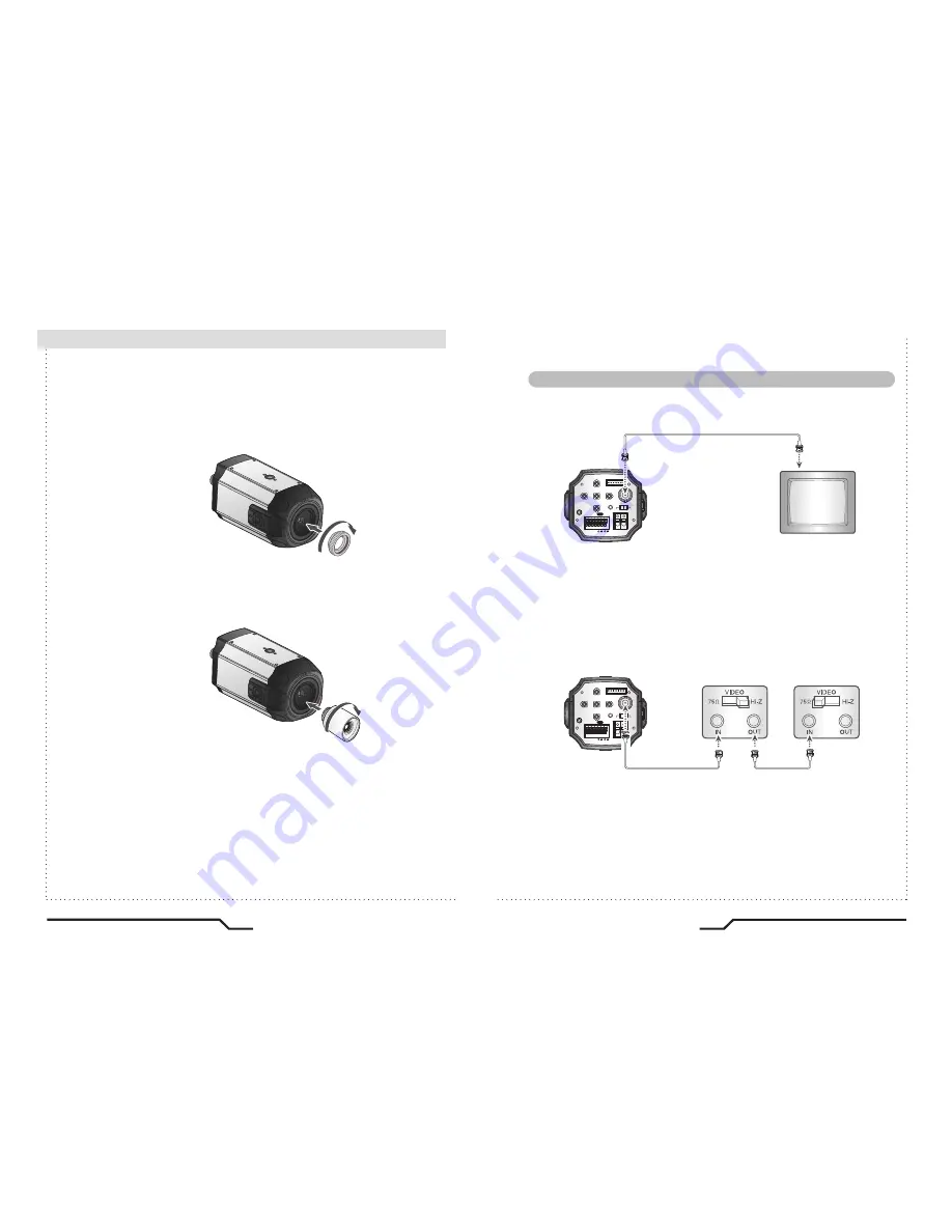
When Using a C Mount Lens

1. Remove the protective cover at the front of this product and turn the CMount

    Adapter clockwise to install it.

2. Turn the C-Mount lens clockwise to install it.

3. Set focus of camera using Back Focus Control Lever of camera side after

    combining C-Mount lens.

Connecting to a monitor

Connect the video output terminal located on the rear of the camera

to the monitor.

• Since the connection procedure may differ depending on the type of monitor

or peripheral device to be connected, refer to the User Manual for the device

to be connected.

• Make sure to turn off the device to be connected before making any connections.
• Turn the 75

/Hi-Z switches of interim display devices to the Hi-Z position,

and the switches of any final device to the 75

 position.

REMOTE

VIDEO OUT

DC

VIDEO

POWER

SET

F.G

AC24V/DC12V

D/N

IN G

M/D

OUT

UTP

OUT

RS485

REMOTE

VIDEO OUT

DC

VIDEO

POWER

SET

F.G

AC24V/DC12V

D/N

IN G

M/D

OUT

UTP

OUT

RS485

CMOS Camera

Monitor

CMOS Camera

End monitor

Intermediate

 Installation Procedures

Summary of Contents for DN83TSPX

Page 1: ...ources other than those specified Do NOT expose this appliance to rain or moisture This installation should be made by a qualified service person and should conform to all local codes The lightning flash with an arrowhead symbol within an equilateral triangle is intended to alert the user to the presence of uninsulated dangerous voltage within the product s enclosure that may be of sufficient magn...

Page 2: ...SK SYNC RS485 SETUP RESET ㆍ EXIT MENU 35 31 32 32 32 33 34 35 35 Troubleshooting 36 Specifications AC24V DC12V 38 Specifications AC230V 39 Contents Features Precautions Overview Installation Procedures Front View Side View Bottom View Rear View 04 06 09 13 09 10 11 12 Lens ㆍWhen Using Auto Iris Lens ㆍWhen Using C CS Mount Lens 13 Connecting a Monitor 17 Connecting Power 18 Control via RS 485 Inter...

Page 3: ...it malfunctioning If the camera emits smoke or is unusually hot for a long period a fire may be caused Do not Install the camera on a surface that can not support it If the camera is installed on an inappropriate surface it may fall and cause injury Do not hold plug with wet hands It could cause an electric shock Do not dis assemble the camera It may result in an electric shock or other hazards Do...

Page 4: ...ra Be careful not to leave fingerprints on the lens cover Do not install or use the camera in an environment where the humidity is high ㆍIf the camera is exposed to spotlight or an object reflecting strong light smear or blooming may occur ㆍPlease check the power supply satisfies the normal specification before connecting the camera It can cause malfunctions to occur If it gets wet wipe it dry imm...

Page 5: ...Adapter 4 Instruction Manual Front View 1 Ultra High Resolution Day Night CMOS Camera Tripod Mounting Bracket Screw Hole Used to fix the Tripod Mounting Bracket to the top of the camera C Mount Lens Adapter Install this adapter to use a C Mount Lens Back Focus clamp screw Loosen the clamp screw with a screwdriver before adjusting the Back Focal length ...

Page 6: ...ris Lens Connector Used to connect Auto Iris Lens plug Tripod Mounting Bracket Screw Hole Used to fix the camera on a bracket or tripod The screw sizes for this hole are as follows 1 4 20 UNC 20 THREAD L 4 5mm 0 2mm ISO standard or 0 197 ASA standard L Side View Bottom View Overview ...

Page 7: ...Right Button Used to move the cursor left or right in the menu screen or to change the value of the selected item D N Input Port GND BW Open Colour You can switch to Day Night Mode by connecting an external signal to this port MD Output Port Motion detection signals are output through this port RS 485 Control Port You can control SETUP MENU through this port by using external controllers like a Re...

Page 8: ...CSMount Lens clockwise to install it And set focus of camera using Back Focus Control Lever of camera side after combining CS Mount lens Use the lens connector shown in the following figure If the dimensions of the connector are not correct it may damage the camera or the lens may not be installed firmly If the lens is too heavy the camera becomes unbalanced and there may be problems Use a lens th...

Page 9: ...amera to the monitor Since the connection procedure may differ depending on the type of monitor or peripheral device to be connected refer to the User Manual for the device to be connected Make sure to turn off the device to be connected before making any connections Turn the 75Ω Hi Z switches of interim display devices to the Hi Z position and the switches of any final device to the 75Ω position ...

Page 10: ...esistance value m 0 018 0 030 0 050 0 078 Voltage drop V m 0 006 0 011 0 018 0 028 When using UTP Cable Connect UTP Unshielded Twisted Pair directly to the UTP output of this camera The camera contains a passive UTP Balun A UTP receiver either passive or active is needed at the Monitor or DVR to connect your UTP cable When connecting the UTP cable make sure the video signal is transmitted over one...

Page 11: ...WDR WHITE BALANCE DAY NIGHT IMAGE ADJ SPECIAL EXIT MENU NORMAL MIDDLE ATW AUTO REMOTE VIDEO OUT DC VIDEO POWER SET F G AC24V DC12V D N IN G M D OUT UTP OUT RS485 UP button SET button LEFT button DOWN button RIGHT button ㆍEXTERNAL ㆍNORMAL SETUP menu PRESETS EXPOSURE WDR WHITE BALANCE DAY NIGHT IMAGE ADJ EXIT MENU ㆍMIDDLE ㆍLOW ㆍRS485 SETUP ㆍCAMERA ID ㆍMOTION ㆍATW ㆍAWB ㆍBACKLIGHT ㆍFREEZE ㆍAUTO SPECIA...

Page 12: ...the function using the UP or DOWN button Change the status using the LEFT or RIGHT button PRESETS Note An item with the icon also has sub menus To select a sub menu press the SET button How to Use the Camera SETUP PRESETS EXPOSURE WDR WHITE BALANCE DAY NIGHT IMAGE ADJ SPECIAL EXIT MENU NORMAL MIDDLE ATW AUTO NORMAL Normal environment INDOOR Indoor environment OUTDOOR Outdoor environment BACKLIGHT ...

Page 13: ... OFF dark parts of the image are most visible COLOR ROLL To control a detector that finds colour fluorescent roll OFF LOW HIGH selectable WDR How to Use the Camera SENS UP When it is night or dark the camera automatically detects the light level and maintains a clear picture if this mode is activated 2X 4X 8X 16X 32X OFF Deactivates the SENS UP function WDR When the image has simultaneous bright a...

Page 14: ...UP PRESETS EXPOSURE WDR WHITE BALANCE DAY NIGHT IMAGE ADJ SPECIAL NORMAL MIDDLE ATW AUTO Select one of the following 5 modes as appropriate ATW The ATW mode continuously monitors INDOOR Select when the colour temperature is between 4000 K and 8500 K OUTDOOR Select when the colour temperature is between 2000 K and 11000 K AWB To obtain the optimum state under the current luminance levels direct the...

Page 15: ...EEZE View still pictures OFF ON selectable FLIP OFF HORIZ VERT BOTH selectable SHARPNESS The outline of the video image becomes cleaner and more distinctive as the level of SHARPNESS increases If the level gose upexcessively however itmayaffectthe videoimageandgeneratenoise The available range of level is 8 8 COLOR GAIN To control the colour level in the video The available range of level is 8 8 G...

Page 16: ... maximum length of the ID is ten characters ㆍYou can choose the ON and OFF with the selector If you select ON the entered camera ID is displayed at the selected position in the video picture normal operation ㆍPlease select the setup button while in On mode ㆍSelect the desired position with the selector Move the cursor to the letter required by using the Set Up button Select an ID from A B Y Z a b ...

Page 17: ...colour DZOOM ZOOM PAN TILT PREVIOUS PAGE 1 0 0 100 100 1 4 100 100 MOTION DETECTION ACTIVITY THR MESSAGE TIME SETUP MOTION ZONE PREVIOUS PAGE 0 25 255 1 3 10 MOTION ZONE SETUP PRIVACY MASK Hide an area you want to hide on the screen ㆍWhite MOTION ZONE Position movement Green MOTION ZONE Size enlargement Red MOTION ZONE Size reduction ㆍFor MOTION ZONE Confirm long press SET button PRIVACY MASK SETU...

Page 18: ...on sets up the camera communication status when controlling the camera through an external control device RS485 SETUP CAMERA PROTOCOL BAUD RATE PREVIOUS PAGE 1 1 255 PELCO D PIXEMMULTIDROP 2400 4800 9600 19200 RESET Resets the camera EXIT MENU VERSION SAVE EXIT DEFAULT CANCEL 7 3 2 7 0 281 EXIT MENU VERSION 7 3 2 7 0 281 SAVE EXIT Saves all the setting menus and then exits DEFAULT Resets the camer...

Page 19: ...le operating your camera refer to the following table If the guidelines do not enable you to solve the problem contact an authorised technician Problem Nothing appears on the screen The image on the screen is dim Check the power connections Check the VIDEO signal line connection Make sure the lens is clean Clean the lens with a soft clean lint free cloth Adjust the monitor contrast brightness cont...

Page 20: ... LOW MEDIUM HIGH OFF HORIZ VERT BOTH ON OFF More than 50dB Composite video output 75 ohm terminated Built in Built in 30 90 RH 10 C to 50 Appro 400g Power Consumption 420mA DC12V Only 350mA AC24V 490mA DC12V SPEC ITEM Image Sensor Signal processing Transfer Format Sync System Effective Pixels Dynamic Range HorizontalResolution Min Illumination Day Night White Balance WB Range Shutter Speed Sens up...

Page 21: ... MENU ...

Page 22: ...TV LTD CCTV House City Park Watchmead Welwyn Garden City Hertfordshire AL7 ILT Tel 44 0 1707 330541 Fax 44 0 1707 330543 www geniecctv com PIXIM True Day Night Bodied Camera Instruction Guide Model DN83TSPX DN83TSPX 12 DN83TSPX 240 ...

Reviews: