


Speed Dome Camera Instruction Manual
45/50
System Initiali
s
ation
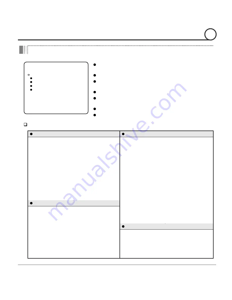
SYSTEM INITIALIZE
------------------------
CLEAR ALL DATA NO
CLR DISPLAY SET NO
CLR CAMERA SET NO
CLR MOTION SET NO
CLR EDIT DATA NO
REBOOT CAMERA NO
REBOOT SYSTEM NO
BACK
EXIT
Factory Defaults
Display Parameters
Camera Parameters
Camera ID
ON
Focus Mode
SemiAuto
PTZ Information
AUTO
Digital Zoom
ON
Action Title
AUTO
Image Flip
OFF
Preset Label
AUTO
Sharpness
16
Alarm I/O
AUTO
Stabilisation
OFF
North Direction
Pan 0
°
White Balance
AUTO
Privacy Zone
Undefined
Backlight
OFF
O
T
U
A
t
h
g
i
N
&
y
a
D
0
5
s
s
e
n
t
h
g
i
r
B
O
T
U
A
s
i
r
I
C
S
E
r
e
t
t
u
h
S
E
L
D
D
I
M
C
G
A
s
r
e
t
e
m
a
r
a
P
n
o
i
t
o
M
Motion Lock
OFF
SSNR
MIDDLE
Power Up Action
ON
SENS-UP
AUTO
N
O
p
il
F
o
t
u
A
Jog Max Speed
120
°
/sec
User-Defined Data
Jog Direction
INVERSE
Preset 1~128
Undefined
Freeze In Preset
OFF
Swing 1~8
Undefined
Park Action
OFF
Pattern 1~4
Undefined
Alarm Action
OFF
Group 1~8
Undefined
Clear All Data
Deletes all configuration data and the system
is set to the factory defaults.
Clear Display Set Initialises all the configuration data for Display.
Clear Camera Set Initialises all the configuration data for
the Camera.
Clear Motion Set Initialises all the configuration data for Motion.
Clear Edit Data
Deletes all the configuration data for Preset,
Swing, Pattern and Group.
Reboot Camera
Reboots the zoom camera module.
Reboot System
Reboots the system.
OSD MENU
4


