Copyright of the European Union is effective (Copyright EU) (c) 2016 GENEREX GmbH, Hamburg, Germany, All rights reserved
TEL +49(40)22692910 - EMAIL [email protected] - WEB www.generex.de (This and all other product datasheets are available for download.)
6
2.
Installation
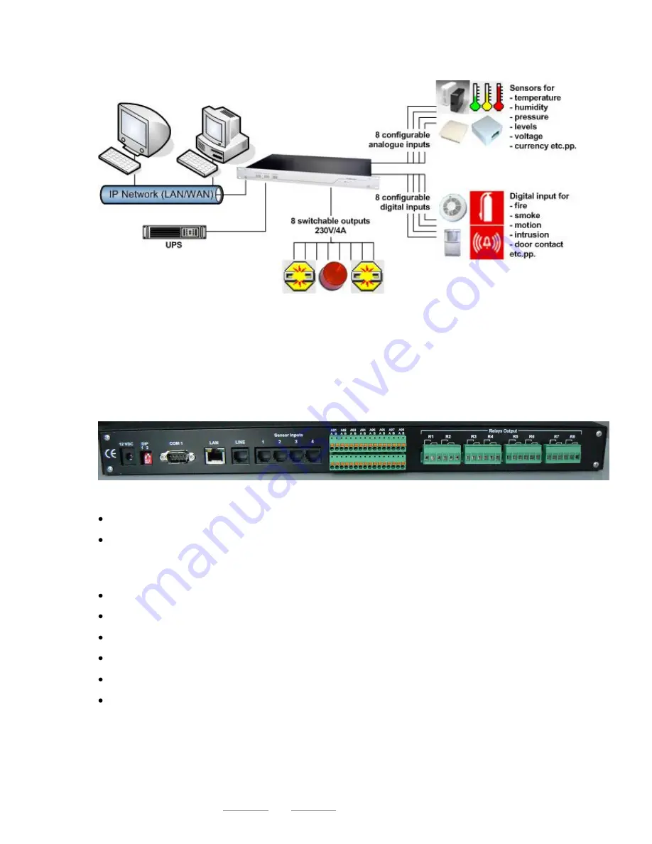
Figure 2:
SITEMANAGER II/v3 with UPS
The figure above shows a typical installation of the SITEMANAGER II/v3 with a UPS connected.
Imagine, that a numerous kind of sensors can be connected to the SITEMANAGER II/v3 and it is
possible to manage all kind of current consuming devices by switching the outputs.
2.1
Connectors and connections Rev.A
The backside of the SITEMANAGER II/v3 incorporates the following connectors as shown below:
Figure 3:
Backside of the SITEMANAGER II/v3
Power supply: Connect the included external power supply unit (DC, 12V).
DIP switch 1,2: With the DIP switches it is possible to change between configuration mode and
normal operating mode. How to use the DIP switches please follow the instructions in section 3
Getting started
– Basic settings.
COM 1 port: If necessary, connect the UPS with the original vendors UPS cable.
LAN connector: Connect the SITEMANAGER II/v3 with an RJ45 cable to the network.
LINE: Port for external RAS service.
4 RJ12 connectors containing 8 analog inputs channels for sensors and other measurment units.
8 digital and 8 analog input sockets.
8 switchable relay outputs.


