General DCS1800HP User Manual Download Page 7

7


SETUP INSTRUCTIONS

CHARGE CONSOLE AND PROBE 
HANDLE/CONTROLLER BATTERIES

To prepare to power the system on for the first time, 
begin by attaching the P16181HP probe to the 
DCS1800-TR probe handle/controller. To make the 
connection, retract the metal collar of the probe 
connector (Fig. 2, Callout 10) to expose the alignment 
key with a dot. Keeping the collar pulled back, align this dot with the dot on the
connector of the probe handle/controller and push the two connectors together. To
secure the connection, push the collar forward and turn it clockwise until tight.

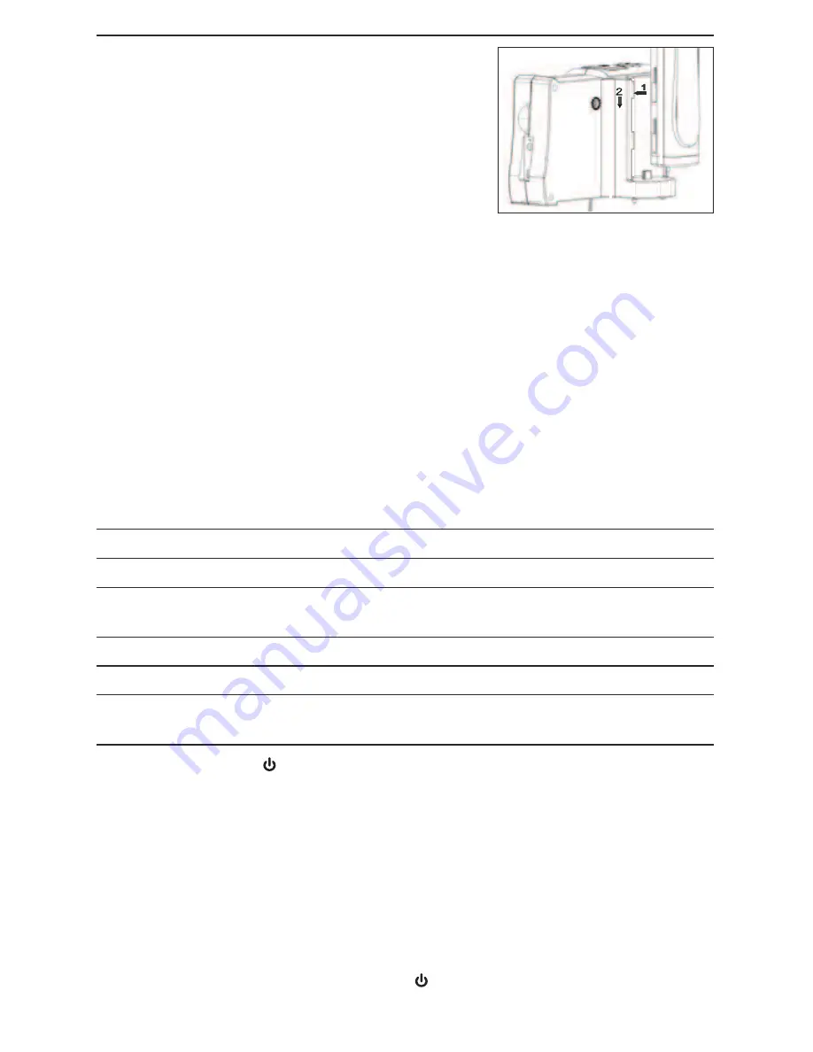
Next, securely attach the probe handle/controller to the back of the DCS1800 console
using the two motions shown above at right. Plug one end of the supplied AC adapter/
battery charger into a 110VAC receptacle. Then swing the black rubber protective flap
away from the right side of the DCS1800 console to expose the AC adapter jack (Fig. 1,
Callout 10). Insert the cylindrical plug at the end of the adapter/charger cable into the 
AC adapter jack. This will begin charging the console’s battery and the probe handle/
controller’s battery at the same time. Next, power on the probe by rotating the probe
handle/controller’s thumbwheel downward until you feel and hear a click.

Table 2. Correlating the color of the LED on the probe handle/controller with its
battery charge

LED COLOR

BATTERY STATUS

COMMENT

Green

ln use

Working under full battery

Dark Red

Low battery

Recharge battery when 

dark red light appears during usage

Oranqe

Charging while in use

Charging while in use

Red

Charging with power off

Charging with power off

None

Full battery with power off

Light dims when

battery is fully charged

Next, press the red the 

button on the console (Fig. 1, Callout 3) and hold it for at least

five seconds. The LCD will illuminate and briefly show a battery charge indicator and
two SD card status advisories (see page 9 for details) superimposed on video being
captured in real time by the camera at the end of the probe. After a few seconds, only
live video will remain.

Practice using the thumbwheel on the probe handle/controller to adjust the intensity of
the camera’s lighting. In a brightly lit room, moving the thumbwheel has a big effect on
the brightness of the LEDs at the tip of the probe, but a much smaller effect on the
brightness of video on the screen. The on-screen impact of changing brightness is more
pronounced in dark environments.

To power off the DCS1800 console, push the 

button and hold it for at least five

seconds.

Summary of Contents for DCS1800HP

Page 1: ...z HIGH PERFORMANCE WIRELESS RECORDING VIDEO BORESCOPE SYSTEM with VGA RESOLUTION PROBE USER S MANUAL DCS1800HP Please read this manual carefully and thoroughly before using this product...

Page 2: ...uctions 9 16 Viewing Live Video on the Console 9 10 Using the Three Control Buttons 10 Attaching the Mirrored Viewing Tip 11 Viewing Live Video on a TV Monitor 11 12 Taking Pictures and Recording Vide...

Page 3: ...to the DCS1800 console Two tables describing all probes compatible with the DCS1800 console can be found on p 18 A thumbwheel on the right side of the DCS1800 TR allows you to adjust the brightness of...

Page 4: ...facing front and two at an angle to reduce glare Operating flexibility is maximized when console is detached from probe In this mode video captured by probe can be sent wirelessly through probe handle...

Page 5: ...TV monitor The cable has RCA plugs at one end and a mini stereo plug at the other end A small flat blade screwdriver for changing the wireless channel of the console and probe This user s manual PRODU...

Page 6: ...de Switches to Preview size of target zooms 2X mode Pressed and held mirrors video Takes a picture No action When setting date time stores jpg photo on SD card increases field value by one unit Starts...

Page 7: ...ating the probe handle controller s thumbwheel downward until you feel and hear a click Table 2 Correlating the color of the LED on the probe handle controller with its battery charge LED COLOR BATTER...

Page 8: ...onsole s LCD resumes showing probe video after a brief delay the two units are already operating on the same channel and there is no need to sync them If detaching the probe handle controller from the...

Page 9: ...d the button again to power the console back on Each time the console is powered on the screen shown below will appear briefly superimposed on live video captured by the camera probe Together the numb...

Page 10: ...Pressing the button a third time rotates the field of view yet another 90 Pressing the button a fourth time restores the original view and extinguishes the red button backlight To remove glare reflect...

Page 11: ...and use your other hand to turn the alignment ring clockwise Keep turning the ring until its leading edge contacts the mirrored viewing tip locking it in place The pair of figures below illustrate th...

Page 12: ...e clip being recorded Pressing and holding the Esc button does not mirror the field of view of the clip being recorded The console will be unable to store videos and pictures if its SD memory card is...

Page 13: ...or through a card reader remember to eject the card from the PC once you are done viewing and or copying the files it contains Depending on your PC s startup settings your computer may fail to restar...

Page 14: ...e the LCD will display the following advisory NO AVOUT CABLE The DATE TIME SETUP line allows you to set the console s calendar and clock Doing so is necessary only if you wish to keep track of your ph...

Page 15: ...s and press the OK Menu button To re disable the function later enter Menu mode scroll down to the AUTO POWER OFF line press the OK Menu button select OFF and press the OK Menu button again to save th...

Page 16: ...OBE Length 1m 3 28 ft Diameter 5 5mm 0 22 in Depth of Field 0 25 to 12 in 6 4 to 300mm Field of View 60 diagonal Resistances To water oil dust per IP67 standard Camera Lighting 4 forward facing LEDs 2...

Page 17: ...damaging the delicate wires and fiber optic cables inside the probe never curl it into a circle with a diameter of less than 6 in The camera head LEDs and thread protector ring are waterproof but not...

Page 18: ...8 COMPATIBLE PROBES The tables below describe and compare all probes compatible with the DCS1800 console COMPATIBLE PROBES Model No SKU Probe Description Camera Head Diameter Probe Length Depth of Fie...

Page 19: ...ance of the exclusive repair and replacement remedies described herein is a condition of the contract for purchase of this product In no event shall General be liable for any incidental special conseq...

Page 20: ...99 TOLL FREE 800 697 8665 e mail sales generaltools com www generaltools com DCS1800HP User s Manual Specifications subject to change without notice 2015 GENERAL TOOLS INSTRUMENTS NOTICE WE ARE NOT RE...

Reviews: