
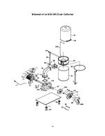


8
6
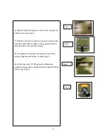
. Attach & Tighten 2 support rods, to base, using 2 hex
bolts for each rod. (Fig. 5)
7.
With the help of an assistant, line up the holes in the
drum assembly with the holes in the support rods and
attached with 2 Hex nut bolts. (Fig.6)
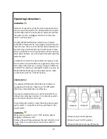
8.
Place gasket in between connector & Drum then
connect together with 8 hex nut bolts. (Fig.7)
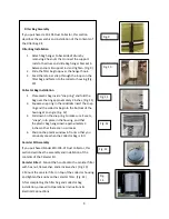
9.
Fit the hose inlet (“Y” fittin
g) on the fan/motor
assembly and secure it in place with the supplied Phillips
head screw. (Fig. 8)
Fig. 5
Fig. 6
Fig. 7
Fig. 8