background image


ASSEMBLY INSTRUCTIONS 

• 

SERIOUS PERSONAL INJURY COULD OCCUR IF YOU CONNECT 

THE MACHINE TO THE POWER SOURCE BEFORE YOUR HAVE 
COMPLETED THE SET UP PROCESS. DO NOT HOOK-UP THE MACHINE 
TO A POWER SOURCE UNTIL INSTRUCTED TO DO SO.  

• BE SURE TO READ AND UNDERSTAND THIS ENTIRE MANUAL. • USE 

CAUTION AND WEAR GLOVES WHEN HANDLING METAL PARTS SUCH 
AS THE BELT CLAMPS, WHICH CAN CUT IF HANDLED CARELESSLY. 


• THE SOUND LEVEL OF THIS MACHINE IS RATED AT APPROXIMATELY 

80-85 DB DURING OPERATION. MAKE SURE THAT ADEQUATE 
HEARING PROTECTION IS USED AND THAT THE OVERALL SOUND 
LEVEL WITHIN THE WORKING ENVIRONMENT IS TAKEN INTO 
CONSIDERATION. 


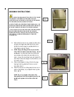
1.


Attach the 4 casters to the underside of the base 
using 4 hex flange head bolts per caster, then 
tighten the bolts using the supplied 8-10 mm 
combination wrench. (Fig.1) 

2.


NOTE

Help with lifting will be needed at this 

time. The fan/ motor assembly is heavy - do not 
overexert.

 Turn the base back over (right side 

up) and place the fan/motor assembly on the 
plate. Line up the mounting holes and attach the 
assembly to the base using 4 hex head bolts, 2 on 
each side. (Fig.2)


3.


Place rubber gasket on top of motor housing 
aligning holes in gasket with holes in motor 
assembly. (Fig 3)


4.


Place the connector on the gasket and secure in 
place using 8 bolts, in pre tapped holes. Tighten 
bolts. (Fig. 4)


NOTE: Do not overtighten the bolts or the 
threaded holes in the base will strip and/or the 
gasket will squeeze out and the outlet will 
crack.


Fig.1 

Fig. 2 

Fig. 3 

Fig. 4 

Summary of Contents for 10-105

Page 1: ...1 1 1 2 HP Dust Collector 10 105 10 105CF 10 105DAS ...

Page 2: ...INTAIN TOOLS IN TOP CONDITION Keep tools sharp and clean for best and safest performance Follow instructions for lubricating and changing accessories 16 DISCONNECT TOOLS before servicing and when changing filters 17 USE RECOMMENDED ACCESSORIES The use of accessories and attachments not recommended by manufacturer may cause hazards or risk of injury to persons 18 AVOID ACCIDENTAL STARTING Make sure...

Page 3: ...s 5 For Your Own Safety 5 Contents of Shipping Carton 6 Tools Required for Assembly 6 Assembly 7 Operating Instructions 10 Changing Bag Filters 11 Recommended Accessories 12 Warranty and Service 13 Parts Breakdown for the 1 1 2 HP Dust Collector with and without Canister 14 1 1 2 HP Dust Collector Parts List 15 ...

Page 4: ... service personnel if the grounding instructions are not completely understood or if in doubt as to whether the tool is properly grounded Use only three wire extension cords that have three prong grounding plugs and three pole receptacles that accept the tool s plug Repair or replace a damaged or worn cord immediately This tool is intended for use on a circuit that has an outlet that looks the one...

Page 5: ...necting the machine to the power supply or cleaning 5 To reduce the risk of electrical shock do not expose dust collector to water or rain 6 Make certain the machine is properly grounded 7 Wear ear protectors ear plugs or muffs approved safety glasses face shield during extended periods of operation 8 To avoid a potentially dangerous situation do not use this equipment to filter flammable vapors o...

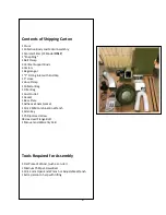
Page 6: ...Cap 1 5 Hose 2 Hose Clamp 1 Collector Bag 1 Filter Bag 1 Dust Outlet 1 Gasket 1 Base Plate 1 Adhesive Foam Gasket 1 10 12 MM Combination Wrench 1 Allen Key 1 Phillips Head Screw 38 Hex Head Flange Bolt 1 Manual and Warranty Card Tools Required for Assembly 1 Flat Piece of Wood such as a ruler 1 Medium Phillips Screwdriver 1 10 12 mm Open End Wrench or Adjustable Wrench 1 Extra person to help with ...

Page 7: ... 4 casters to the underside of the base using 4 hex flange head bolts per caster then tighten the bolts using the supplied 8 10 mm combination wrench Fig 1 2 NOTE Help with lifting will be needed at this time The fan motor assembly is heavy do not overexert Turn the base back over right side up and place the fan motor assembly on the plate Line up the mounting holes and attach the assembly to the ...

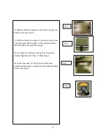
Page 8: ...n the drum assembly with the holes in the support rods and attached with 2 Hex nut bolts Fig 6 8 Place gasket in between connector Drum then connect together with 8 hex nut bolts Fig 7 9 Fit the hose inlet Y fitting on the fan motor assembly and secure it in place with the supplied Phillips head screw Fig 8 Fig 5 Fig 6 Fig 7 Fig 8 ...

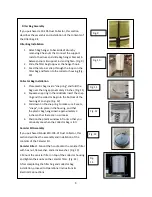
Page 9: ...ing and the collector bag into the bottom of the housing at an angle Fig 12 3 Pull down on the snap ring to make sure it seats snaps into place in the housing and that the plastic bag hangs down approximately 3 inches so that there are no air leaks 4 Position the plastic window in front so that you can easily see when the collector bag is full Canister Kit Assembly If you purchased Model 10 105 CF...

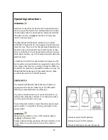
Page 10: ...e other tools are running Turning the Machine On Off This machine is intended for indoor use only All Models Before hooking up to the power source make sure that the switch is in the off position ON OFF SWITCH The model 10 105M1 10 105CF M1 Dust collector is equipped with a simple rocker style On Off switch featuring a removable lock out safety key To prevent unauthorized use or unintentional star...

Page 11: ...our nearest General distributor for the full line of General Dust Collector Hoses and Accessories Customize your installation and obtain maximum performance with General dust hoods hoses clamps fittings and blast gates Cleaning the Filter 10 105CK WARNING Never perform maintenance on this machine before turning switch off and removing plug from power source Failure to comply may cause serious inju...

Page 12: ...t or postage prepaid to General or to a nearby distributor repair center or other location designated by General For further details call our service department at 1 844 877 5234 or info gipowerproducts com Along with the return of the product being claimed for warranty a copy of the original proof of purchase and a letter of claim must be included a warranty claim form can also be used and can be...

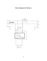
Page 13: ...13 Electrical diagram for DAS units ...

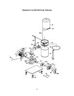
Page 14: ...14 Schematic for 10 105 Dust Collector ...

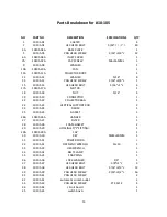
Page 15: ... 1 22 10105 22 COLLECTOR BAG 1 23 10105 23 VERTICAL SUPPORT ROD 2 24 10105 24 DRUM 1 25 10105 25 GASKET 1 26A 10105 26A HANGER 1 27 10105 27 FILTER 1 28 10105 28 FOAM GASKET 2 29 10105 29 HOSE INLET Y FITTING 1 29A 10105 29A CAP 1 30 10105 30 KEY 5MM 40MM 1 31 10105 31 POWER CORD 1 32 10105 32 OPEN END WRENCH 13 10 1 33 10105 33 HEX WRENCH 1 34 10105 34 BELT CLAMP 1 35 10105 35 SNAP RING 1 36 1010...

Page 16: ...16 46 10105 46 ON OFF switch with automatic function 1 47 10105 47 switch box B 1 48 10105 48 fastener 1 ...

Reviews: