


MS3002 Manual v.200909
Page 26
workpiece. The base of the saw has
four mounting holes. Bolt the base of
the miter saw (1) to the work surface
(5), using the fastening method as
shown in Fig K.
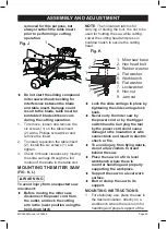
Fig. L
3/4 in.
plywood
NOTE
: Mounting hardware is not
included with this tool. Bolts, nuts,
washers and screws must be purchased
separately.
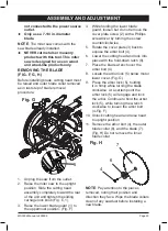
2. For portable use, place the miter
saw on a 3/4 in. thick piece of
plywood. Bolt the base of the miter
saw securely to the plywood using
the mounting holes on the base. Use
C-clamps to clamp this mounting
board to a stable work surface at the
worksite. (Fig. L)
NOTE
: If a miter saw stand is used,
please follow all instructions shown in
that product’s instructions for proper
mounting.
BEVEL STOP ADJUSTMENT
WARNING
To avoid injury from an accidental
start, make sure the switch is in the
OFF position and the plug is not
connected to the power source.
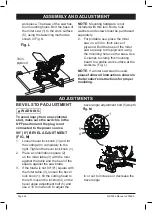
90° (0°) BEVEL ADJUSTMENT
(FIG. M)
1. Loosen bevel lock knob (1) and tilt
the cutting arm completely to the
right. Tighten the bevel lock knob (1).
2. Place a combination square (2)
on the miter table (3) with the ruler
against the table and the heel of the
square against the saw blade.
3. If the blade is not 90°(0°) square with
the miter table (3), loosen the bevel
lock knob (1), tilt the cutting head to
the left, loosen the locknut (4) on the
bevel angle adjustment bolt (5) and
use a 10 mm wrench to adjust the
bevel angle adjustment bolt (5) depth
in or out to increase or decrease the
bevel angle.
Fig. M
1
4
5
2
3
ASSEMBLY AND ADJUSTMENT
ADJUSTMENTS