PLACEMENT WITHIN THE SHOP
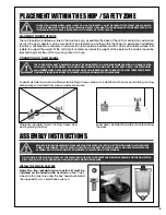
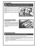
The unit should be installed as close to the dust source(s) as possible. The base of the unit is mounted on casters and
as such the dust collector can be moved from one location to another within the shop if a permanent installation
location is not practical or desired. In all cases the unit should be installed on a flat, sturdy and stable surface that
is able to support the weight of the unit and its contents, as well as the weight of the operator. The casters should be
blocked to prevent the unit from moving when it is in use.
PLACEMENT WITHIN THE SHOP / SAFETY ZONE
9
THIS DUST COLLECTOR MODEL 10-950 IS HEAVY. DO NOT OVER-EXERT. A HOIST OR FORKLIFT WITH STRAPS SHOULD BE USED
TO LIFT THIS MACHINE. TO LIMIT THE RISK OF SERIOUS INJURY OR DAMAGE TO THE MACHINE, ANY EQUIPMENT USED TO LIFT
THIS MACHINE SHOULD HAVE A RATED CAPACITY IN EXCESS OF 183 LBS (83 KG).
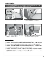
Wherever possible avoid running hoses and
ducting along the floor.
Keep hoses and ducting safely mounted along
the walls.
CONNECTION OF THE MACHINE
To avoid accidents as well as damage to ducting or hoses, plan your installation with hoses and ducting running
along walls or mounted from above wherever possible.
THE 10-950 METAL DUST COLLECTOR CANNOT BE CONNECTED TO A MACHINE EQUIPPED WITH A COOLANT RESER-
VOIR. ALSO, THE 10-950 MODEL IS NOT DESIGNED TO REMOVE WOOD DUST OR WET DUST. DUE TO THE POTENTIALLY
HIGH TEMPERATURE CHIPS, PLEASE USE ONLY HOSE AN ALUMINUM HOSE. FAILURE TO FOLLOW THESE SAFETY RULES
CAN RESULT IN SERIOUS INJURY TO THE USER AS WELL AS DAMAGE TO THE MACHINE.
ASSEMBLY INSTRUCTIONS
TIP: TO INSTALL THE SWIVEL CASTERS, LAY THE MACHINE ON ITS SIDE. TO PREVENT SCRATCHES OR DAMAGE ON THE COLLECTOR,
FIRST PLACE A PIECE OF CARDBOARD ON THE GROUND UNDER THE MACHINE.
INSTALL THE SWIVEL CASTERS
BEFORE STARTING THE ASSEMBLY, MAKE SURE THAT THE SWITCH IS IN THE “OFF” POSITION AND THAT THE POWER
CORD IS UNPLUGGED. DO NOT PLUG IN OR TURN ON THE DUST COLLECTOR UNTIL YOU HAVE COMPLETED THE
ASSEMBLY AND INSTALLATION STEPS DESCRIBED IN THIS SECTION OF THE MANUAL.
A
B
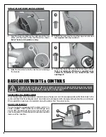
Note: The two lockable swivel casters B must be
installed on the handle side as shown.
Attach the 4
wheels to the machine using the hex. head bolts
A
and
the supplied 12 mm combination wrench.
Summary of Contents for 10-950
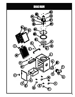
Page 15: ...15 DIAGRAM ...
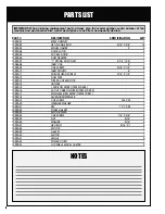
Page 17: ...17 NOTES ...


