10
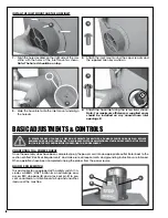
1.
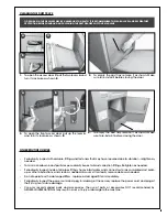
Align the holes located on the right side of the ma-
chine with the holes of the inlet mount as shown.
Note: The hole A should be on top.
2.
Attach the inlet mount using the cap screws
A
and
the supplied Allen key as shown.
INSTALL THE INLET MOUNT AND THE HOSE INLET
A
3.
Slide the hose inlet onto the inlet mount and align
the holes
A
.
4.
Attach the hose inlet using the screw
A
as shown.
Note:
For maximum efficiency, a supplied cover
should be installed on any unused hose inlet
openings, B
A
A
B
A
B
C
BASIC ADJUSTMENTS & CONTROLS
CONNECTING TO A POWER SOURCE
Once the assembly steps have been completed, plug the power cord into an appropriate outlet. Refer back to the
section entitled “Electrical Requirements” and make sure all requirements and grounding instructions are followed.
When operations have been completed unplug the planer from the power source.
ON/OFF POWER SWITCH
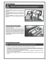
This dust collector is equipped with a safety switch. It in-
cludes a GREEN “START” button
A
, an extra-large easy
access RED stop panel
B
, and a lock-out pin
C
to pre-
vent unwanted or unintentional start-up and unauthor-
ized use of the machine.
TO REDUCE THE RISK OF SHOCK OR FIRE DO NOT OPERATE THE UNIT WITH A DAMAGED POWER CORD OR PLUG. REPLACE
DAMAGED CORD OR PLUG IMMEDIATELY. TO AVOID UNEXPECTED OR UNINTENTIONAL START-UP, MAKE SURE THAT THE POWER
SWITCH IS IN THE OFF POSITION BEFORE CONNECTING TO A POWER SOURCE.
A
Summary of Contents for 10-950
Page 15: ...15 DIAGRAM ...
Page 17: ...17 NOTES ...


