background image

Integrated L-Band Up/Dn Converter


LT3600


CG-1309


 Page 13 

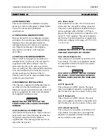
2.4.6 External 10 MHz Input (J2) 

This connector is a BNC female. The male 
mate (not supplied) should be compatible with 
the 50-ohm coax used to connect to the system. 
 

2.4.7 SSPB Interface (J6) 

This connector is a 9-pin female miniature type 
“D” connector with standard #4-40 female 
screw-lock hardware mounting. The mating 
shell, pins, and strain relief are not supplied. 
Outputs are open collector and inputs have 
internal 1K full PS to +5V.  The pin-out is as 
follows: 

Pin 1 

SSPB Band Control Output -  


(Low = Lo Band) 

Pin 2 

Amplifier Fault - Open (Hi) = ALM 

Pin 3 

Thermal Alarm Input –  


Open (Hi) = ALM 

Pin 4 

Lock Alarm Input - Open (Hi) = ALM 

Pin 5 

Up/Dn Converter Ground  

Pin 6 

SSPB Attenuator/Enable Control –  


(Lo = Enable) 

Pin 7 

Not Used 

Pin 8 

SSPB Detector Input + Analog 0-5V 

Pin 9 

SSPB Detector Input – Analog 0-5V 


2.4.8 Remote Serial I/O Interface (J7) 

This connector is a 9-pin male miniature type 
“D” connector with standard #4-40 female 
screw-lock hardware mounting. The mating 
shell, pins, and strain relief are not supplied. 
The electrical interface to this connector is for 
a standard RS-422/485 bus. This port may be 
reconfigured for RS-232 as shown below.  For 
bus protocol requirements, refer to Section 3-3. 
The convention used for the signals is a logic 
Hi for Mark (Rest) and a logic Lo for Space. 
The pin-out is as follows for RS-422/485: 

Pin 1 

Rx - 

Pin 2 

Rx + 

Pin 3 

Tx + 

Pin 4 

Tx - 

Pin 5 

Ground 

Pin 6 

Alarm Relay:  Common 

Pin 7 

Alarm Relay:  Normally Closed 

Pin 8 

Not Used 


Pin 9 

Alarm Relay:  Normally Open 


Port J7 may be reconfigured for RS-232 interface 
by changing the following jumpers locations on the 
main board inside the converter: 
Serial Port 

RS-422/485 

RS-232 

JP3 
TXD SER 0 
RXD SER 1 
(Standard) 

Jumpers On 
1-2


5-6  7-8 

9-10 11-12  
17-18 

Jumpers On 
13-14 
15-16 

JP3  
TXD SER 1 
RXD SER 0 

3-4 5-6 7-8  
9-10 11-12 
19-20 

13-15 
14-16 

JP2 Remove 

Install 

The pinout for RS-232 is as follows: 

Pin 1 

Not Used 

Pin 2 

Rx + 

Pin 3 

Tx + 

Pin 4 

Not Used 

Pin 5 

Ground 

Pin 6 

Alarm Relay:  Common 

Pin 7 

Alarm Relay:  Normally Closed 

Pin 8 

Not Used 


Pin 9 

Alarm Relay:  Normally Open


2.4.9 High Stability 10 MHz Reference 
Output (J1) (Optional Connector)


This connector is a BNC female. BNC jumper 
cable is supplied with this option for 
connection to J2. 


2.5 OPERATIONAL CHECK 

To verify that the basic functions of the unit are 
operational, it is recommended that the 
following check-out procedure be followed 
prior to final system integration. If there are 
any questions regarding performing the 
indicated operations, refer to Section 3-3. 


2.5.1 Setup 

Connect the unit to a primary power source and 
turn on the power switch at the front of the 
unit. Verify that the power led is illuminated. If 
the power led is not illuminated, check the 
power cord and fuse. A spare 3.15 A fuse is 
provided inside the power connector. 


Switch the primary power off and connect the 
IF out, LB in, IF in and the LB out at the rear 
of the chassis to J3, J4, J9 and J10 respectively. 
Re-establish the primary source of power.  The 
Front display will light and status will be 
displayed. 

Summary of Contents for LT-3600 SERIES

Page 1: ...RIES 1915 Harrison Road Longview Texas 75604 EXPORT CONTROL WARNING Do not disclose this document or its contents to non U S Persons or transmit this document or its contents outside the United States...

Page 2: ...the defective product at VertexRSI shall disclose that such defects exist and have not been caused by misuse neglect improper handling alteration or accident VertexRSI reserves the right to make prod...

Page 3: ...on 12 2 4 Electrical Connections 12 2 4 1 Power Input 12 2 4 2 L Band Output J10 12 2 4 3 IF Input J9 12 2 4 4 IF Output J3 12 2 4 5 L Band Input J4 12 2 4 6 External 10 MHz Input J2 13 2 4 7 SSPB Int...

Page 4: ...l 22 4 3 8 Up Converter Spectrum Control 22 4 3 9 SSPB Band Control 22 4 3 10 Set SSPB Gain Attenuation 22 4 3 11 Enable Up Converter 22 4 3 12 Enable Down Converter 22 4 3 13 Satellite Memory Store 2...

Page 5: ...LCD Display 7 Figure 1 2 Rear Panel 7 Figure 3 1 Front Panel Controls and Indicators 14 Figure 3 2 Menu Listing 15 Figure 3 3 Satellite Memory 16 Figure 3 4 StarSwitch Display Auto Selection 17 Figure...

Page 6: ...ile performing these procedures and never work alone With power applied to the unit and the cover removed be aware that a rotating fan is operating 1 2 GENERAL INTRODUCTION This manual provides operat...

Page 7: ...to right Grounding Lug GND Power Connector Optional 10MHz high stability reference output J1 10 MHz reference input J2 IF Out J3 L Band In J4 On Off Switch for Dc output on J4 SW2 Cooling Fans Down C...

Page 8: ...U C 15VDC 5th Digit 6th Digit 7th Digit L Band Ports 10 MHZ Ref Out StarSwitch Ready 0 SMA Female 0 No Output 0 No 1 N Type Female 1 U C D C 1 Yes 2 U C Only 3 D C Only Note If connected to a StarSwit...

Page 9: ...mum 3rd Order Intermodulation for 2 car each at 0 dBm o p 40 dBc Spurious at 0 dBm output 55 dBc Non Carrier 60 dBm Transmit Spectrum Sense Non Inverting or Inverting Noise Power Density 125 dBm Hz DO...

Page 10: ...kHz Parameter Memory Storage Non Volatile EEPROM L Band Output Phase Noise at 100 Hz Offset 66 dBc Hz at 1 kHz Offset 76 dBc Hz at 10 kHz Offset 86 dBc Hz at 100 kHz Offset 96 dBc Hz at 1 MHz Offset...

Page 11: ...nternal Electronics Power 25 watts StarSwitch Interface Connectors Options DB 15 Female Remote Serial Interface Standard RS 422 RS 485 J7 DB 9 Male External SSPB Monitor and Control J6 DB 9 Female DC...

Page 12: ...4 ELECTRICAL CONNECTIONS All electrical connections are made to the rear panel of the unit The following describes the rear panel connectors and its interface requirements The chassis ground is a 10...

Page 13: ...arm Relay Common Pin 7 Alarm Relay Normally Closed Pin 8 Not Used Pin 9 Alarm Relay Normally Open Port J7 may be reconfigured for RS 232 interface by changing the following jumpers locations on the ma...

Page 14: ...TA FOR VARIOUS PARAMETER SETTINGS THE APPLICABLE NUMBER IS ENTERED AT THE CURSER UNDERLINE AND THEN IS PRESSED TO ACCEPT THE CHANGE THE DISPLAY WINDOW SHOWS THE VARIOUS SETTINGS FOR THE UNIT CONTROL A...

Page 15: ...PE FACTOR SET LCL RS 485 ADDRESS AND STATUS Unit Address xx xx 422 Mode Front Panel SW v5 20 FP Alarm Tone Muted UC 1000 250 15 0 dB DC 1500 625 30 0 dB SOFTWARE VERSION AND ALARM CONTROL DEFAULT MENU...

Page 16: ...RM AND STORE CHANGE TO EACH FIELD AND LEAVE EDIT MODE AFTER LAST FIELD ENT UC0 1200 000 20 0 dB DC0 1200 000 30 0 dB LCL 0 1 UC1 1000 125 30 0 dB DC1 1500 125 45 0 dB UC9 1500 875 25 0 dB DC9 1300 875...

Page 17: ...n the system Upon switchover to the backup converter the display will change to Figure 3 5b indicating STBY in the Activity Window Under normal operation the Summary Alarm would only be ON if there we...

Page 18: ...itch Alarm however does not activate the Summary Alarms and the Backup Converter will still backup an Online Converter when it is powered down Figure 3 8 shows the Backup Converter display after Conve...

Page 19: ...ence is not detected Active Mode 4 LNB N A Act OK Bad N A Disable Alarm if LNB or BDC is not present Activate for LNB supply current Alarm select in Edit Mode LNB supply current is within acceptable r...

Page 20: ...Units marked with Rev A on the rear panel support the new protocol 4 1 LT 3600 SERIAL INTERFACE The serial interface format to the Up Dn Converter for RS 422 is identical to the RS 485 format except t...

Page 21: ...cters Range 0950 to 1950 MHz for Std and Extended Band units Where xxxx x Fifth character is fractional MHz as follows 0 0 0 MHz 1 0 125 MHz 2 0 250 MHz 3 0 375 MHz 4 0 500 MHz 5 0 625 MHz 6 0 750 MHz...

Page 22: ...disable or mute the transmitter and x 1 to enable or un mute the transmitter 4 3 12 Enable DOWN Converter aaCBx Where x 0 to disable or mute the DOWN Converter and x 1 to enable or un mute the DOWN Co...

Page 23: ...in 125 kHz increments 4 4 3 Level Status aaS2 Returns S2MLffppeett Where M ASCII hex Char MSN of bitmapped status F indicates no alarm in group D7 Low SSPB Lock Alarm D6 Low SSPB Thermal Alarm D5 Low...

Page 24: ...verter enable Range 0 disable 1 enable ee 2 Character SSPB current detection Range 00 to 30 0 3 0 A N 0 for SSPB Disable 1 SSPB Enable 4 4 5 Set Cable Slope Factor aaFx Where x numeric character Range...

Page 25: ...er of the Satellite Memory location bbbb Frequency for the Up Converter cccc Frequency for the Down Converter dddd Gain for the Up Converter eeee Gain for the Down Converter y ASCII character making u...

Page 26: ...CCA Software Revision History 7 72 StarSwitch Menu and Status Update 7 71 Added RS 485 address to Fractional Frequency Status 7 70 High Low gains with signs M C changes July 05 7 56 1950 MHz limit inv...

Reviews: