500-0646A 23
2.2.8 Subreflector
Assembly
Step 1.
Identify a notch at the top of the subreflector. Make sure the subreflector is properly
mounted with the notch toward the topside.
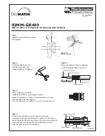
Step 2.
The subreflector has been factory assembled to the two subreflector brackets using
the four subreflector clips with 1/4” x 3/4” [6.35mm x 19.05mm] stainless steel
hardware. The subreflector brackets are mounted to the subreflector seat with
3/8” x 1” [9.525mm x 25.5mm] stainless steel hardware (See Figure 18).
Step 3.
Place the factory-assembled subreflector on the end of the feed boom and secure it
using the 3/8” x 1-1/4” [9.525mm x 44.45mm] stainless steel hardware. (see Figure
18).
Summary of Contents for 500-0646
Page 8: ...500 0646A vi LIST OF TABLES Table 1 Tool List 3...
Page 23: ...500 0646A 14 Figure 11 Radial Beam Installation...
Page 24: ...500 0646A 15 Figure 12 Reflector Lacing Assembly...
Page 26: ...500 0646A 17 Figure 13 Reflector Panel Assembly...
Page 28: ...500 0646A 19 Figure 14 Reflector Panel Assembly Order...
Page 31: ...500 0646A 22 Figure 16 Feed Boom Assembly...
Page 33: ...500 0646A 24 Figure 17 Feed Boom Assembly Supports...
Page 37: ...500 0646A 28 Figure 20 Feed Assembly Figure 21 Feed Alignment...
Page 44: ...500 0646A 35 Figure 29 Azimuth Resolver with Bracket Figure 30 Azimuth Resolver side view...
Page 54: ...500 0646A A 3...