500-0646A 11
Step 5.
Install the elevation drive assembly to the pedestal base by installing the rod-end pin
and cotter pin.
Step 6.
Secure the elevation jack drive assembly to the elevation jack support by installing
the shoulder screws.
Step 7.
Install the elevation jack motor following the steps used to install the azimuth jack
motor (see Section 2.2.2).
CAUTION!
IF THE MOTOR IS USED ON THE ELEVATION JACK, POSITION IT SO
THAT THE CONDUIT BOX HOLE IS FACING DOWN TO PREVENT
WATER FROM SEEPING INTO THE CONDUIT BOX. THE MOTOR
MAY NEED TO BE ROTATED BACK AND FORTH UNTIL BOTH
COUPLING HALVES LINE UP AND MESH TOGETHER.
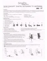
Figure 8. Installing the Elevation Jack
Summary of Contents for 500-0646
Page 8: ...500 0646A vi LIST OF TABLES Table 1 Tool List 3...
Page 23: ...500 0646A 14 Figure 11 Radial Beam Installation...
Page 24: ...500 0646A 15 Figure 12 Reflector Lacing Assembly...
Page 26: ...500 0646A 17 Figure 13 Reflector Panel Assembly...
Page 28: ...500 0646A 19 Figure 14 Reflector Panel Assembly Order...
Page 31: ...500 0646A 22 Figure 16 Feed Boom Assembly...
Page 33: ...500 0646A 24 Figure 17 Feed Boom Assembly Supports...
Page 37: ...500 0646A 28 Figure 20 Feed Assembly Figure 21 Feed Alignment...
Page 44: ...500 0646A 35 Figure 29 Azimuth Resolver with Bracket Figure 30 Azimuth Resolver side view...
Page 54: ...500 0646A A 3...