General Dynamics
4096-387
SATCOM Technologies
1.2M Ku-BAND Rx/Tx SERIES 1123
16
SECTION IV
ANTENNA POINTING
4.0 INITIAL
POINTING
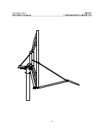
The 1.2 meter reflector contains a 22.6° elevation offset look angle. Therefore,
when the reflector aperture is perpendicular to the ground, the antenna is actually
looking 22.6° in elevation. Refer to Figure 2.
Step 1:
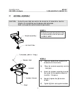
Place an inclinometer on the reflector support angle as shown in Figure 2.
Step 2:
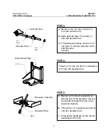
Adjust the reflector up or down in elevation by turning the two ½" hex nuts
at the elevation channel until the desired elevation is read on the
(inclinometer reading plus 22.6° = elevation angle). Note: Be sure that the
elevation pivot hardware (5 places) is loose enough to allow adjustment
without damaging (bending) the elevation rod. Snug the hardware.
Step 3:
Azimuth Adjustment: With the electronics set to acquire the satellite,
rotate the antenna in azimuth until the satellite is found. Snug the azimuth
adjustment hardware.
Step 4:
Peak the antenna signal by fine adjustments made in both azimuth and
elevation until the optimum signal is achieved.
Step 5:
Tighten all hardware used for adjustment.
Step 6:
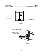
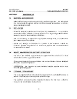
Scribe a line next to the Azimuth and Elevation indicators to mark the
satellite location as shown in Figure 3 and 4.
Step 7:
If desired, locate a secondary satellite by repeating steps 1 through 5.
Mark this satellite location as described in step 6 and then return to the
primary satellite by returning azimuth and elevation to the first set of scribe
lines made.

