Operation
Owner’s Manual for 50 Hz Air-Cooled Generators
9
Section 3: Operation
Site Prep Verification
It is important that the generator is installed in such a way
that the airflow into and out of the generator is not
impeded. Verify that all shrubs or tall grasses have been
removed within 3 ft. (0.91 m) of the intake and discharge
louvers on the sides of the enclosure. It is also important
that the generator is not subject to water intrusion. Verify
that all potential sources such as water sprinklers, roof
run-off, rain gutter down spouts and sump pump
discharges are directed away from the generator
enclosure.
Turn the generator OFF before performing maintenance.
Remove 7.5 Amp fuse, T1 and T2 battery charge fuses,
and disconnect battery cables to prevent accidental start
up. Disconnect the NEGATIVE (-) cable first, then
disconnect the POSITIVE (+) cable. When connecting
the cables, connect the POSITIVE cable first, the
NEGATIVE cable last.
Side Compartment
Local codes may require that the side compartment be
locked. A hasp is provided so the owner/operator can
secure the side compartment with a padlock. Check local
codes for side compartment locking requirements.
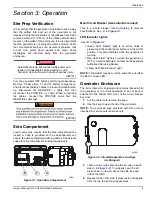
Figure 3-1. Open Side Compartment
Main Circuit Breaker (Generator Disconnect)
This is a 2-pole breaker rated according to relevant
specifications. See “A” in
LED Indicator Lights
See “B” in
•
Green LED “Ready” light is on when utility is
present and the control panel button is in the AUTO
position. This also indicates when the generator is
running.
•
Red LED “Alarm” light is on when the generator is
OFF or a fault is detected. Contact an Independent
Authorized Servicing Dealer.
•
Yellow LED “Maintenance” light.
NOTE:
Yellow LED may be on at the same time as either
the Red or Green LED.
Generator Enclosure
The lid is locked for shipping and remains locked while
the generator is in normal operation. A set of keys is
attached to the bottom left corner of the circuit breaker
box door.
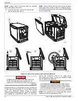
1.
Cut the cable tie to remove the keys.
2.
Use the keys to open the lid of the generator.
NOTE:
The enclosed keys provided with this unit are
intended for service personnel use only.
Figure 3-2. Circuit Breaker Box and Keys
(As Shipped)
3.
There are two locks securing the lid, one on each
side (A in
). To properly open the lid,
press down, on the lid, above the side lock and
unlock the latch.
4.
Repeat for the other side. If pressure is not applied
from the top, the lid may appear stuck.
Automatic start-up. Disconnect utility power and
render unit inoperable before working on unit.
Failure to do so will result in death or serious injury.
(000191)
DANGER
(000182)
WARNING
001241
A
B
C
000867
Summary of Contents for 10 kVA
Page 31: ......


