background image

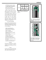
amplifier cooling and unrestricted airflow 
from the reflex port. This can be done by 
making the recess 7.5 centimeters (3") wider 
than the subwoofer. Place the subwoofer 
into the right end of the recess with the 
driver side facing the room. This leaves 
sufficient 7.5 centimeters (3") of free space 
on the reflex port side. The height and depth 
of the recess should not be any bigger than 
is needed to fit the subwoofer flush with the 
wall surface. 

Sensitivity Adjustment

The subwoofer requires input sensitivity 
alignment to the source to obtain a 
correctly balanced system. The input 
sensitivity control is located on the 
connector panel of the subwoofer. An 
input voltage of -6 dBu with a -6 dBu input 
sensitivity setting will produce 100 dB SPL 
@ 1 m in free field.

Setting The Phase Control

Incorrect phase alignment between the 
main loudspeakers and subwoofer causes 
a drop in the frequency response of the 
whole system at the crossover frequency. 
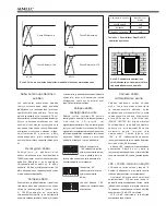
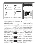
The graphs above (Fig. 5) show the effect 
of phase difference to the frequency 
response.

The phase difference between the main 

loudspeakers and subwoofer at the listening 
position is dependent upon the position of 
the subwoofer, so the phase adjustment 
should be done only after the preferred 

position is found. Acoustic measuring 
equipment is required for accurate system 
alignment. If this equipment is not available, 
the following coarse phase matching can 
be applied.

Coarse Phase Adjustment 

Method

Connect an audio frequency signal generator 
to one of the inputs of the 7050C and set 
it to feed a 85 Hz signal to the system. 
Alternatively, you can use a 85 Hz signal 
fom a suitable audio test recording. Make 
sure you connect (even temporarily) a main 
loudspeaker to the corresponding output 
on the subwoofer, so that the test signal is 
properly reproduced by both subwoofer and 
main loudspeaker.

Toggle the -180° phase 
switch (DIP 4 from left) 
"ON" and "OFF", and set it 
to the position which gives 

the lowest sound level at the listening position. 

Next toggle the -90° 
phase switch (DIP 3) "ON" 
and "OFF", and again set 
it to the position which 

gives the lowest sound level.

Finally, set the -180° 
phase switch (DIP 4) to 
the opposite setting and 
deactivate the test signal.

Phase Correction Method 

With Test Equipment

The following procedure matches the phase 
between the subwoofer and the main 
loudspeakers using a frequency analyser 
and a pink noise generator. Connect a 
high grade measuring microphone to the 
analyser and feed pink noise into one of 
the inputs of the subwoofer. Position the 
microphone at the listening position and 
adjust the input sensitivity of the subwoofer 
until frequencies below and above 85 Hz are 
reproduced at equal level. Then adjust the 
phase control switches for the maximum 
dip of at least -6 dB at the crossover 
frequency (85 Hz).

Change the -180° switch to the opposite 

setting. The phase should now be set 
correctly and the frequency analyser should 
show a smooth response around 85 Hz. 

Using The LFE +10 dB 

Function

The LFE channel is usually recorded 10 dB 
lower than the main channels so that there 
is 10 dB of extra level (headroom) available.

Most AV processors automatically add 10 

dB to the LFE channel to restore the level in 
the LFE channel but some medium format 
mixing consoles and many smaller consoles 
do not have the facility to apply the +10 dB 
gain to the LFE. To overcome this limitation 
Genelec subwoofers provide a +10 dB LFE 
gain selection.

Figure 5. The effect of phase difference between the subwoofer and the main loud-
speakers 

Phase Difference: 0°

85 Hz

Phase Difference: 180°

85 Hz

Phase Difference: 270°

85 Hz

Phase Difference: 90°

85 Hz

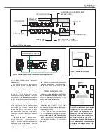
Figure 6. Flush mounting the 
subwoofer. Note the clearance needed 
on the reflex port side.

Table 1. Suggested Bass Roll-Off  
settings

Subwoofer placement

Bass Roll-Off 

setting

Near to a wall

-4 dB

In a corner

-8 dB

Flush mounted

-4 dB

4

3

2

1

7

6

5

Summary of Contents for 7050C

Page 1: ...Genelec 7050C Active Subwoofer Operating Manual Käyttöohje 7000 Series ...

Page 2: ...t signal is detected from the source There is a slight delay in the automatic powering up If this is undesirable the ISS function can be disabled by setting the ISS switch on the connector panel to OFF In this mode the subwoofer is powered on and off using the power switch on the connector panel The ISS SENSITIVITY LOW switch lowers the triggering sensitivity of the ISS function This can be necess...

Page 3: ...ith two subwoofers Flush mounting pos 5 generally works well MAINS INPUT 50 60 Hz 150 W 100 240 V 7050C ACTIVE SUBWOOFER SERIAL NUMBER OUT IN BYPASS ROLL OFF PHASE 270 8 dB 4 dB ON ISS LFE 10 dB 6 0 3 12 3 LFE IN 6 4 INPUT dBu PRODUCING 100 dB SPL 1 m ISS SENSITVITY LOW 90 180 ELECTRIC SHOCK HAZARD DO NOT OPEN DO NOT SUBJECT TO WATER OR MOISTURE NO USER SERVICEABLE PARTS INSIDE REFER SERVICING TO ...

Page 4: ...in loudspeaker Toggle the 180 phase switch DIP 4 from left ON and OFF and set it to the position which gives the lowest sound level at the listening position Next toggle the 90 phase switch DIP 3 ON and OFF and again set it to the position which gives the lowest sound level Finally set the 180 phase switch DIP 4 to the opposite setting and deactivate the test signal Phase Correction Method With Te...

Page 5: ...t different Bass Roll Off settings 7050C 2 channel system 5 channel system 8020 8030 M030 8010 8020 Room volume up to 75 m3 2647 ft3 Maintenance No user serviceable parts are inside the subwoofer Any maintenance of the unit must only be performed by qualified service personnel Guarantee This product is supplied with a two year guarantee against manufacturing faults or defects that might alter the ...

Page 6: ...gnment 0 90 180 270 Infrasound protection Overload protection features Sum LFE 10 dB Power amplifier Subwoofer in LFE in Highpass 85 Hz Subwoofer in Bypass Analogue in 1 5 Analogue out 1 5 For each analogue input Subwoofer driver and enclosure Crossover lowpass 120 Hz Sensitivity 6 12 dB DIP switches ...

Page 7: ...elow 24 Hz Input channels 5 LFE Low pass frequency for inputs 1 5 85 Hz Low pass frequency for LFE IN input 120 Hz Input connectors XLR female pin 1 pin 2 pin 3 gnd Input impedance 10 kOhm balanced Midband rejection 400 Hz 50 dB High pass frequency for outputs 1 5 85 Hz Output connectors XLR male pin 1 pin 2 pin 3 gnd Output gain 0 dB Bass Roll Off control in 4 dB steps 0 to 12 dB 26 Hz Phase matc...

Page 8: ... o o f e r i n k ä y n n i s t y m i s e s s ä valmiustilasta on pieni viive Jos tämä ei ole hyväksyttävää ISS toiminto voidaan deaktivoida kääntämällä ISS kytkin asentoon OFF Tällöin subwooferin käynnistys ja sammuttaminen tehdään liitinpaneelissa olevalla painikkeella ISS SENSITIVITY LOW katkaisin alentaa ISS toiminnon reagointiherkkyyttä Tämän toiminnon käyttö voi olla tarpeen jos subwoofer käy...

Page 9: ... ANTOLIITTIMET BASS ROLL OFF KYTKIMET VAIHE ISS JA LFE 10 dB VIRTAJOHDON LIITIN VIRTAKYTKIN OTTOLIITTIMET SUBWOOFERIN OHITUSKYTKIMEN BYPASS LIITIN MAINS INPUT 50 60 Hz 150 W 100 240 V 7050C ACTIVE SUBWOOFER SERIAL NUMBER OUT IN BYPASS ROLL OFF PHASE 270 8 dB 4 dB ON ISS LFE 10 dB 6 0 3 12 3 LFE IN 6 4 INPUT dBu PRODUCING 100 dB SPL 1 m ISS SENSITVITY LOW 90 180 ELECTRIC SHOCK HAZARD DO NOT OPEN DO...

Page 10: ...ä subwooferin 180 vaihekytkin neljäs kytkin vasemmalta lukien vuoroin päälle ja pois ja jätä se siihen asentoon jolla bassotoisto kuuntelupaikalla on vaimeampi Tee samoin 90 vaihekytkimelle kolmas kytkin vasemmalta lukien Lopuksi käännä 180 vaihekytkin vastakkaiseen asentoonsa Vaiheen säätö mittalaitteiden avulla Vaiheen säädössä voidan käyttää m y ö s t a a j u u s v a s t e a n a l y s a a t t o...

Page 11: ...oimia saa suorittaa vain valmistajan valtuuttama huoltohenkilöstö Älä avaa subwooferin koteloa tai irrota laitteesta mitään osia Laitteen saa kytkeä ainoastaan maadoitettuun pistorasiaan Huomaa että vahvistin ei ole täysin jännitteetön ellei virtajohtoa ole irrotettu pistokkeesta Subwooferin ympärillä pitää olla riittävä vapaatila lämmön haihduttamiseksi Huolto Kaikki huolto ja korjaustoimet on an...

Page 12: ...nt 0 90 180 270 Infrasound protection Overload protection features Sum LFE 10 dB Power amplifier Subwoofer in LFE in Highpass 85 Hz Subwoofer in Bypass Analogue in 1 5 Analogue out 1 5 For each analogue input Subwoofer driver and enclosure Crossover lowpass 120 Hz Sensitivity 6 12 dB DIP switches ...

Page 13: ...ännät 5 LFE Alipäästösuodin ottoliittimille 1 5 85 Hz Alipäästösuodin kanavalle LFE IN 120 Hz Ottoliittimet XLR naaras pin 1 pin 2 pin 3 gnd Ottoimpedanssi 10 kOhm symmetrinen Keskitaajuuksien vaimennus 400 Hz 50 dB Ylipäästösuodin antoliittimille 1 5 85 Hz Antoliittimet XLR uros pin 1 pin 2 pin 3 gnd Antoliitäntöjen toistokaistan vahvistus 0 dB Bass Roll Off säätö 4 desibelin portain 0 12 dB 26 H...

Page 14: ......

Page 15: ......
Page 16: ...ech Circle Natick MA 01760 USA Phone 1 508 652 0900 Fax 1 508 652 0909 Email genelec usa genelec com In China please contact Beijing Genelec Audio Co Ltd Room 101 1st Floor Building 71 B33 Universal Business Park No 10 Jiuxianqiao Road Chaoyang District Beijing 100015 China Phone 86 10 5823 2014 Post code 100015 Email genelec china genelec com In Sweden please contact Genelec Sverige Ellipsvägen 1...

Reviews: