background image

BASIC PREPARATIONS 

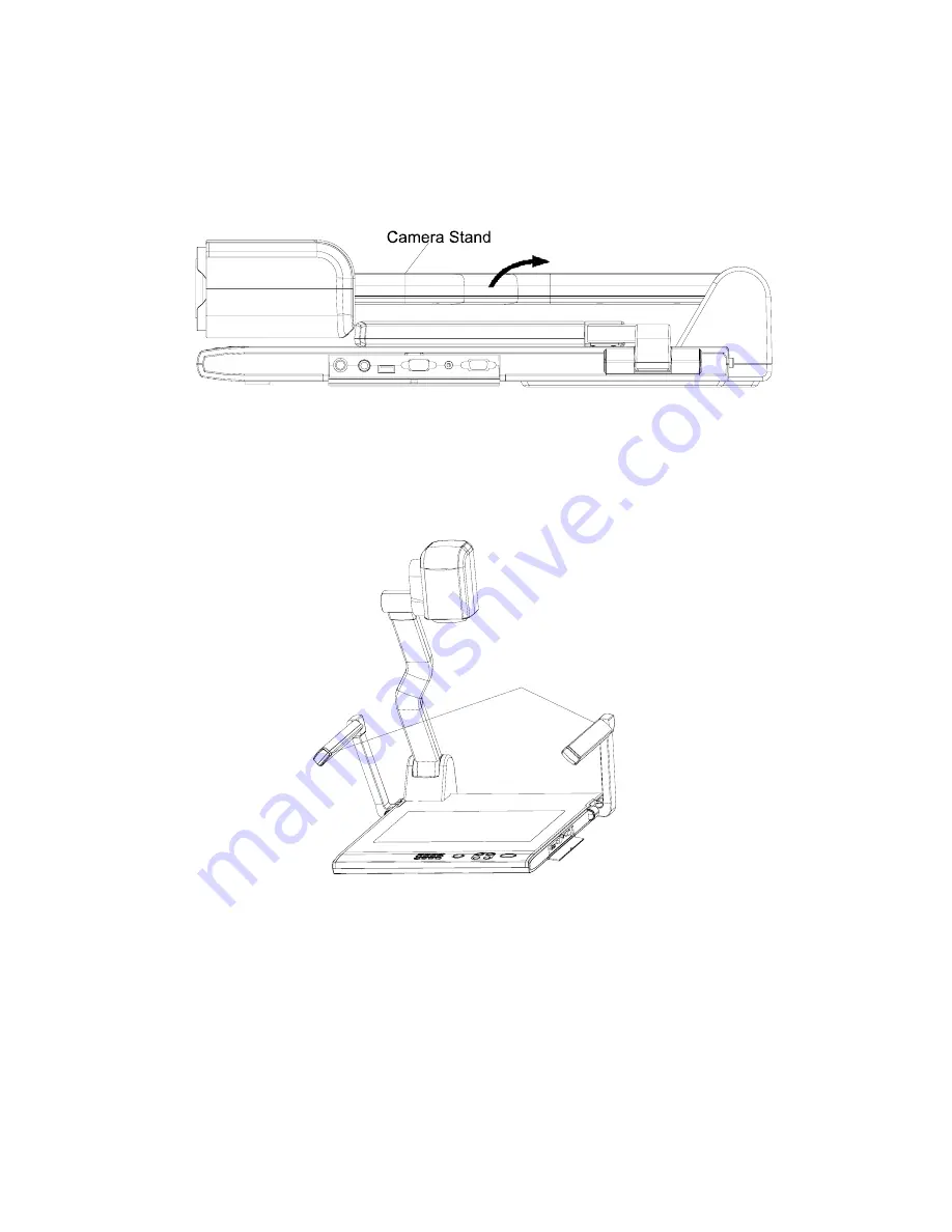
1.  Use one hand holds the base of the visualiser, use the other hand 

carefully lift up the camera stand of the unit. 

 
2.  Open the arm lights and rotate the camera head until they are in 

proper positions. 

Arm lights


3.  Making connections: 
Before making any connection,

 turn off all the power

, including 

power of the visualiser and the equipment to be connected. 
Step 1: Connect power source. 
First connect the power cord to the 

12V IN 

connector.  

 
Step 2: Connect to the projector. 

7


Summary of Contents for Vision 6100

Page 1: ...o spill water or other liquids onto the unit or allow combustible or metallic objects to get inside the cabinet Unplug the visualiser from the wall outlet when it is not being used for a long period of time Clean the cabinet with a soft cloth lightly moistened with a mild detergent solution Clean the lens carefully with an air spray or soft dry cloth to avoid scratching it When the lamps flash or ...

Page 2: ... THE STAGE 13 LIGHT 14 ADJUSTING IMAGE SIZE 14 WORKING WITH NEGATIVES 14 FOCUSING 15 FREEZING IMAGE 15 BRIGHTNESS ADJUSTMENT 15 WHITE BALANCE ADJUSTMENT 15 AUTO ADJUSTMENT 15 TEXT IMAGE MODE 16 COLOR AND B W MODE SWITCH 16 SWITCHABLE VIDEO INPUTS 16 SWITCHABLE RGB INPUTS 16 PROJECTOR ON STANDBY 16 PROJECTOR INPUTS SELECTION 17 IMAGE REVERSION 17 IMAGE SPLIT 17 DYNAMIC STATIC MODE SWITCH 17 TITLE F...

Page 3: ...ghts Camera Camera stand Back light Remote control slot Operation panel Stage Connectors Connectors Button instruction CONTROL PANEL T POWER LAMP AUTO CCD PC1 PC2 VIDEO Mir Frz Neg Title Far Ppw Pin W 6100 6100 6100 POWER Control the visualiser On Off Mir V Reverse the image Frz Freeze the image Neg Display film negatives Title Freeze the top 1 8 of the screen D S Switch between static mode and dy...

Page 4: ...ntrol the arm lights and back light AUTO To auto adjust white balance and auto focus T W Increase and decrease the magnification Remarks Frz Title D S and Split functions are only available on PROJECTOR OUT BUTTON INSTRUCTION Button function instruction sheet Button Instruction Fold Setup Instruction Indicator Instruction S Video Video CCD PC1 PC2 Auto Adjust Color Brightness and Focus POWER Press...

Page 5: ...ghts and back light FREEZE Freeze the image NEG Display film negatives MIRROR V Reverse the image SPLIT Image split function D S Switch between static mode and dynamic mode XGA Switch between XGA 1024 x 768 and SVGA 800 x 600 mode B W Switch between color mode and B W mode TITLE Freeze the top 1 8 of the screen PROJECTOR POWER Control the projector On Standby PROJECTOR INPUT Projector input signal...

Page 6: ...FREEZE TITLE D S and SPLIT functions are only available on PROJECTOR OUT port CONNECTIONS 1 AUDIO OUT 2 VIDEO OUT 3 S VIDEO OUT 4 VIDEO AUDIO IN 5 VIDEO IN 6 S VIDEO AUDIO IN 7 S VIDEO IN 8 PC AUDIO IN USB PROJECTOR MIC VIDEO OUT AUDIO AUDIO OUT S VIDEO IN VIDEO RGB IN AUDIO IN RS232 Side Panel 9 PROJECTOR Connector 10 COMPUTER OUT 11 COMPUTER IN 12 POWER OUT IN 13 PROJECTOR RS232 Connector 14 MIC...

Page 7: ...he arm lights and rotate the camera head until they are in proper positions Arm lights 3 Making connections Before making any connection turn off all the power including power of the visualiser and the equipment to be connected Step 1 Connect power source First connect the power cord to the 12V IN connector Step 2 Connect to the projector 7 ...

Page 8: ... 9 pin to make the connection between the projector and the visualiser Some projector models may require a converter cable in addition to this standard RS232 cable to connect to the projector control port for the pin locations and shape of some projectors control port connector may be different from the connector of a standard RS232 cable After the visualiser is connected to the projector you can ...

Page 9: ...ep 2 where the RGB cable comes out from the visualiser and goes to the projector After the connections as steps 2 3 4 are made input signals from the computer visualiser CCD and S Video are going to the RGB1 input on the projector and will be displayed on the projector screen as RGB1 These signals can be seen in turn when pressing CCD PC1 PC2 and VIDEO on the control panel of the visualiser AUDIO ...

Page 10: ...les capturing still images video streams from the visualiser to the computer Special software is required for this operation 4 Turn on the power by pressing the POWER button RS 232 connector USB connector of the computer of the computer USB cable RS 232 cable Side Panel USB PROJECTOR MIC RGB IN AUDIO IN RS232 Video in Projector Color monitor S VIDEO AUDIO OUT OUT AUDIO VIDEO S VIDEO VIDEO IN IN AU...

Page 11: ...display images with the USB interface which includes displaying static and dynamic pictures snapping dynamic images and playback the dynamic images with the Windows Media Player or its own player A Insert the CD ROM that comes with your visualiser into the CD ROM drive If Autorun is enabled on your system then the Software Setup window will be displayed automatically as below If it does not start ...

Page 12: ...e visualiser Remarks DirectX9 0 is not necessary to install it is mainly for computer print screen function Please pay attention to the following 1 Computer hardware requirement CPU Pentium 4 RAM 256M or above USB 2 0 port Hard disk 40G or more 2 Operating system Windows 2000 or above If the operating system is Windows 2000 should install SP4 If the operating system is Windows XP should install SP...

Page 13: ...visualiser when installing 2 Please use USB2 0 from visualiser accessories WORKING ON THE STAGE 1 Place your material on the working surface 2 Select the enlargement required with the T and W keys 3 Adjust the focus with the Near and Far keys or AUTO key WORKING OUTSIDE THE STAGE For showing 3 dimensional objects just place them on the working surface and adjust the T or W and AUTO keys If the obj...

Page 14: ...rder to reduce or enlarge the image size displayed on the screen press the T or W button WORKING WITH NEGATIVES The visualiser is automatically set to display normal materials on the screen when the power is on To display negatives turn on the backlight by pressing the LAMP key and then press the Neg button to display the film negatives Press the Neg button again to display normal materials in the...

Page 15: ...function is not available on S Video and Video output BRIGHTNESS ADJUSTMENT If the image effect is not satisfactory you can adjust the brightness to get a better image effect Use the BRIGHT or BRIGHT button to adjust the brightness To increase the brightness press the BRIGHT button To decrease it press the BRIGHT button To go back to the initial brightness press the AUTO button WHITE BALANCE ADJUS...

Page 16: ...ns among different sources such as Camera CCD COMPUTER IN and RGB IN Notes COMPUTER OUT always outputs COMPUTER IN signals PROJECTOR ON STANDBY Press the POWER button to turn on the visualiser s power and press the Ppw button to turn the projector power on To turn the projector standby after use press the Ppw button more than 2 seconds and then the projector enters to the stand by mode On the remo...

Page 17: ...d instruction IMAGE REVERSION Press the Mir button once to V reverse the image and the vertically mirrored image will be displayed Press the Mir button again to exit On the remote control please press the MIRROR button IMAGE SPLIT Press SPLIT the image will be split into two images One is the current captured image the other is a frozen image of the last image Press the SPLIT button again to exit ...

Page 18: ...he saved images then press the numerical button to show the corresponding image For example Press 2 to display the second image At this status the function under each numeric key is not available Press RECALL again to exit this mode On the remote control INFRARED REMOTE CONTROL The visualiser s remote control can control the camera from different angels Please note that an infrared remote control ...

Page 19: ...ntrol the visualiser from a computer connected with a RS232 connector A Connect the computer and the visualiser with the computer RS 232 cable 9 pin to 9 pin B Select Start Program VideoCap VideoCapx xx x xx is software s version to open the software C Click Control Panel under Capture D Select the COM port COM1 or COM2 and you can control the visualiser by clicking the buttons on the menu Toolbar...

Page 20: ...g box or click icon on the toolbar then input the file name in dialog box If you want to set the time limit for the capture select Capture Set Time Limit to set the time limit Click Start Capture to start capture and click Stop Capture or icon on the toolbar to stop capture If you have set the time limit it will stop automatically when the time is up The video file is AVI format C Set the Frame Ra...

Page 21: ...hen the indicator of Current RS 232 Connection Status is green that means the connection between the visualiser and the computer s RS232 connector is good If the indicator is red please check if the RS232 cable is connected correctly When all the cables are connected correctly please click Projector to select your projector model under the drop down list then click Send If you cannot find your par...

Page 22: ...01 00 00 60 01 00 Then use the same input rule to input other code b If the data is in the character string format input character string For example the POWER ON code in the SHARP C40 50 projector manual is P O W E 1 is space is enter In the POWER ON box input POWR 1 0d 0a Remarks There are 3 spaces after POWER 0d 0a is enter Input other codes in the same way c If the data is in the numerical val...

Page 23: ...Data the pin 5 is TXD Transmitted Data the pin 4 is GND Ground Other pins are not defined The pin location information of the projector is provided by the projector s manufacturer The projector s RS232 control port normally has RXD pin TXD pin and GND pin the name may be different The parallelism of each data pin is shown as follows Visualiser s RXD pin Projector s TXD pin Visualiser s TXD pin Pro...

Page 24: ...r s operating panel to check if the control code that the program received is the same as the sending code If the receiving code is same to the sending code the input codes are correct If the visualiser cannot control the projector please do the following 1 Check to see if the source control codes of projector are correct 2 Check to make sure the connection between the visualiser and the projector...

Page 25: ...2 Carefully fold the camera stand down to the front panel Cautions a Don t lay the unit down flat b Don t try to stand it on its rear or sides 25 ...

Page 26: ...GA 800 x 600 Total Pixels 470 000 RGB Output Pixels 780 000 22 x optical zoom 10 x digital zoom Lens F 1 6 3 7mm f 3 9 85 8 mm Focus Iris Auto manual selectable White balance Auto Image split Yes Negative positive conversion Yes Black white and color selection Yes Image Freeze Yes Mirror Yes Arm light 1 5 W LED lamps x 2 Lights Back light LED lamp NOT THIS WAY 26 ...

Page 27: ... 6 pin PS 2 USB port USB 2 0 Optional Power requirements 12V 4A external AC adapter Folded 20 0 x 16 1 x 4 7 Setup 20 0 x 20 9 x 22 4 Dimension W x D x H Packing 25 6 x 21 2 x 9 1 Weight N W 5 5Kg 12 1lbs G W 7 5Kg 16 5 lbs Accessory AC power cord RGB cable Audio Video cable S Video cable Computer RS232 cable 9 pin to 9 pin Projector RS232 cable 6 pin to 9 pin USB cable Optional Audio convert cabl...

Reviews: