Instructions for Use: GEV019-100
Page 27
6
Operating Instructions
6.1 Installation
Pre-Installation Considerations:
The GeVentor is designed to be either floor-standing or wall mounted. The GeVentor can be mounted vertically on a pipe stand,
at an angle or horizontally on a flat surface. A risk assessment associated with the positioning of the GeVentor installation is to be
determined by the intensive care clinician.
Inspect the GeVentor for any damage that may have occurred during transportation and handling before installation.
DANGER
Parts and/or components that have been damaged
or tampered with during shipping are not to be
used.
Installation Procedure:
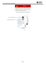
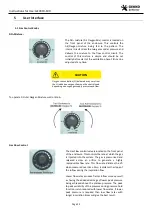
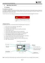
The following procedure is recommended (refer to the diagram below for components):
1.
Remove GeVentor from packaging, outside of the ICU.
2.
Clean unit as per clinical guidelines.
3.
Install battery isolation fuse in fuse mount on bottom of enclosure.
4.
Securely attach accessories.
5.
Connect air gas supply connection into the air connection port.
6.
Install GeVentor Expiration Valve (on expiration side of the patient circuit)
7.
Connect oxygen gas supply connection into oxygen connection port.
8.
Connect inspiration hose into 22 mm inspiration hose port.
9.
Connect expiration hose into 22 mm expiration hose port after the Bio-filter.
10.
Install the PEEP valve above the GeVentor Expiration Valve.
11.
Plug GeVentor into electrical supply mains power and switch the unit on.
12.
Check if HMI is operational.
Note:
The GeVentor’s
Battery Isolation fuse is stored within the Instructions for Use, contained by a plastic envelope.
Air Connection
Oxygen Gas
Connection
GeVentor Expiration Valve
Expiration Hose and Bio-filter
Connection Port (22 mm)
Electrical Power
Connection Port
Human Machine Interface (HMI)
PEEP Valve
(not shown)
Inspiration Hose
Connection Port (22 mm)


