11. Check the axial clearance of connecting rod, move the
rod forward and backward, and measure the axial clearance
with the micrometer (Fig. 179).
12. Detach the connecting rod cap and check the oil film clear-
ance (refer to Chapter 4 Section2).
13. Remove the piston and the connecting rod compo.
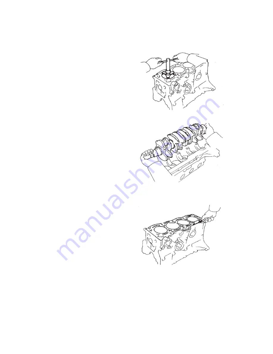
(1) Clear all the carbon deposit around the cylinder opening
with a reamer (Fig. 40).
(2) Put boot on the connecting rod bolt with the short hose in
order to protect the crankshaft from being damaged.
(3) Push the piston, connecting rod compo. and the upper
bearing shell out of the top of cylinder block. Put the connect-
ing rod bearing, connecting rod and connecting rod cap
together. Locate the piston and connecting rod compo. in
proper sequence.
14. Check the axial clearance of crankshaft (refer to Chapter
5 Section2).
15. Detach the main bearing cap and check the oil film clear-
ance.
16. Remove the crankshaft
(1) Lift and take out the crankshaft.
(2) Remove the main bearing upper half and the upper thrust
washer off the cylinder block. Locate the main bearing cap,
main bearing and thrust washer in proper sequence (Fig. 41).
(II) Check
1. Clean the cylinder block. Clear the residue of cylinder
gasket off the topside of cylinder block with the gasket
scraper. Clean completely the cylinder block with soft brush
and solvent (Fig. 42). Check whether there’re damages or
cracks on the topside of cylinder block or in the main bearing
seat, screw hole, oil passage and internal cavity.
2. Check the flatness of topside of cylinder block. Measure the
flatness of surface contacting the cylinder head gasket with
the precision ruler and the thickness feeler. The maximal warp
tolerance is 0.05mm. If the warp is bigger than the maximal
value, replace the cylinder block (Fig. 43). There has been no
deformation over-difference in the application of Geely
engines. If over-difference occurs, refine the flatness by grind-
ing the topside of cylinder block. The cylinder compression
ratio may go up if the block top surface is over-ground.
3. Check whether there’s vertical scratch upon the cylinder. If
there’s deep scratch, the 4 cylinders shall be re-bored.
Replace the cylinder block if necessary (Fig. 44).
4. Check the inside diameter of cylinder. There’re 3 dimension groups, named as group “1”, “2” and “3” of standard diam-
eter (Fig. 45). Print the group number upon the bottom of cylinder block.
Measure at position of A, B and C the diameters in the thrust direction and in the transverse axis direction with the cylinder
diameter gauge (Fig. 46).
Fig. 41 Locate the Main Bearing cap, the
Main Bearing and the Trust Washer
Fig. 40 Clear the Carbon Deposit around
the Cylinder Port with Reamer
Fig. 42 Clear the Residue of Gasket on
the Upper Surface of Cylinder Block
35
Summary of Contents for JL481Q
Page 1: ......
Page 9: ...5 Fig 3 Components Assembly Drawing of MR479Q MR479QA Engine ...
Page 10: ...6 Fig 4 MR479Q MR479QA Engine and Its Power System ...
Page 11: ...7 Fig 5 Assembly Drawing of Engine and Its Auxiliaries MR479Q MR479QA ...
Page 12: ...8 Fig 6 Electronic Control Fuel Injection System in Engine MR479Q MR479QA ...
Page 13: ...9 Fig 7 Front view of Engine JL481Q MR481QA ...
Page 14: ...10 Fig 8 Sectional elevation of Engine JL481Q MR481QA ...
Page 15: ...11 Fig 9 Electronic Control Fuel Injection System in Engine JL481Q MR481QA ...


