


GERC_RLY Rev 2 Wiring and Usage manual
January 9, 2007
6
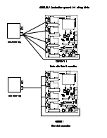
For such machines, an EStop Override switch is required to “trick” the GERC into thinking that
all is well. This must be a normally open switch and
really
should be a momentary switch. It
must also be placed within easy reach of the keyboard, as you’ll be holding this Override
switch down with one hand will jogging via the keyboard with the other.
The actual series of operations to clear such an event is as follows.
1. Press and hold the EStop Override switch.
2. Reset the GERC_RLY by toggling the AllStop/Reset switch (as described below)
3. Reset your controller program (if required)
4. Jog the offending axis
J5 110 VAC power input
The GERC_RLY has an onboard power supply, but needs 110 Volts AC. This must be
supplied through a power switch and fuse, in accordance with local regulations. It is the outer
two connections that are used; the inner terminal is used for isolation only. A suitable value for
a fuse would be 1 amp, quick blow. Typical current consumption is 100 ma.
J6-9 Relay Connections
J6
X axis power connector
J7
Y axis power connector
J8
Z axis power connector
J9
A axis power connector
These connectors are wired to the relay contacts.
DC power from the motor’s power supply comes in to pin 1 of the connector, and then to the
Normally Open relay contact.
The Common relay contact is attached to the connector’s pin 2, and then to the Gecko’s pin2.
The Normally Closed relay contact is connected to a power resistor, used for dynamic braking.
The other end of this power resistor goes to pin 3 of these connectors, which is then connected
to the power supply negative (aka, “ground”).
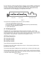
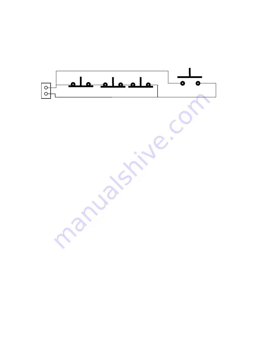
EStop Switch Limit Switches EStop Override Switch
Figure 4
J4