Gecko G3 0 Series Manual Download Page 2


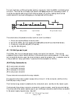
GERC_RLY  Rev 2 Wiring and Usage manual 

January 9, 2007 

1

All the standard legal disclaimers that have ever been written apply to this document. 


If you are not completely proficient in electrical wiring and familiar with local 

ordinances, you should not proceed. 
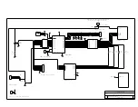
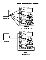
 

Design Theory


The Gecko G320 and G340 controllers are fabulous devices, but have one minor little 
annoyance - the Error/Reset pin. The operation of this pin is somewhat confusing, and the 
usage even more so.  
 
The newest version of the Gecko 3x0 devices ease the use of this pin by allowing a person to 
wire all the pins in a system together, but this is still, in my opinion, an incomplete and 
inflexible solution.  
 
Looking at the various circuits available from a number of sources, I decided that none of them 
precisely suited my needs and so decided to create yet another design. Considering that the 
problem was mostly one of 

logic 

and only partly electronics, I decided to use a microcontroller.  

 
My design goals were these.  
 

  Automatically provide the 5 second reset required at powerup.  


I don’t think, in this day and age of electronics, I should have to stand around and wait 
for a light to go off. 


  Fault all the axes should a single 

active

 axis fault.  


If something bad happens such that an axis faults, it’s obviously important to turn 
everything off.  The part may still be rescued and possible damage to the machine or 
tooling is eliminated. 


  Provide a means to disable all the motors without having to resort to a poweroff.  


Turning on big power supplies, like those found in servo supplies, puts a strain on many 
of the components in the supply.  I wanted a means of resetting/disabling things without 
the “shock” of simply turning it off. 


  Provide a means to disable a single axis without disturbing the fault detection logic.  


Sometimes I like to combine CNC movement with manual adjustment.  For example, on 
a piece of material of unknown composition, I may manually adjust the Z axis until I’m 
confident of the depth of cut.   

Summary of Contents for G3 0 Series

Page 1: ...Gecko G3x0 Error Reset Controller Relays included version Rev 2...

Page 2: ...gic and only partly electronics I decided to use a microcontroller My design goals were these Automatically provide the 5 second reset required at powerup I don t think in this day and age of electron...

Page 3: ...ervo electronics fail in such a manner simply saying to the Gecko via pin5 please stop will not work causing extreme badness However for those people who for whatever reason choose not to add relays t...

Page 4: ...e total consumption exceed 200 ma J2 EStop output The EStop output allows the GERC_RLY to alert the controller typically a PC or an intelligent break out board that something bad has happened Technica...

Page 5: ...Geckos Using figure 1 below as a guide connect a wire from the X Y Z and A points of J3 to Pin 5 of the relevant Gecko Four Geckos four wires Note These inputs are a direct unprotected connection to...

Page 6: ...r will be ineffective The EStop switch carries relay power and as such the contacts cannot be shared with any other device If an EStop switch is to be used to turn off the lathe or mill motor for exam...

Page 7: ...is must be supplied through a power switch and fuse in accordance with local regulations It is the outer two connections that are used the inner terminal is used for isolation only A suitable value fo...

Page 8: ...a power resistor connected across the motor terminals This connection is actually through the Gecko not directly to the motor but the nature of the Gecko output stage is such that this is the correct...

Page 9: ...e LED for that axis is ON steady With all axes enabled all LEDs are on steady With all axes disabled no LEDs are on Normal operation then is all LEDs on Reset Any time the unit is reset the LED for an...

Page 10: ...k in sequence X LED then Y LED then Z LED then A LED then X LED again Note Once the EStop condition is cleared the GERC_RLY requires a reset either by toggling the AllStop Reset switch or by a power c...

Page 11: ......

Page 12: ...in Zin Ain R6 R9 1 2 3 4 J3 IN1 1 IN2 2 IN3 3 IN4 4 IN5 5 IN6 6 IN7 7 IN8 8 VS 9 OUT1 18 OUT2 17 OUT3 16 OUT4 15 OUT5 14 OUT6 13 OUT7 12 OUT8 11 COM CATH 10 U3 ULN 2803A Xout YOut Zout Aout VEStop Xer...

Page 13: ...2 are ELECTRONICS S1 SW SPDT Front Panel PCB D1 LED LED D2 LED LED 1 2 3 4 5 6 7 14 13 12 11 10 9 8 J12 S2 SW SPDT S3 SW SPDT S4 SW SPDT LED LED S1 S2 S3 S4 S5 1 2 3 4 5 6 7 14 13 12 11 10 9 8 J11 XLE...

Page 14: ...ELECTRONICS R10 4r7 VRelay ES_In A_In VRelay K1 P B T90 D5 50sq100 0 To Motor To Power 1 2 3 J9 0 To Motor To Power 1 2 3 J8 VRelay K2 P B T90 R11 4r7 Z_In R12 4r7 D6 50sq100 0 To Motor To Power 1 2...

Page 15: ...ocument Number REV B GERC_RLY 2 Title GERC with relays power supply are ELECTRONICS Heatsink VEStop 1 2 3 J5 6 4 3 1 7 9 10 12 T1 MICROTRAN D9 1n5820 D10 1n5820 C7 220u C10 220u C8 220u IN 1 OUT 3 G N...

Page 16: ......

Page 17: ......

Page 18: ......

Page 19: ......

Page 20: ......

Page 21: ......

Reviews: