background image

CH1

CH2

CH3

CH4

CH5

CH6

+18

+12

+9

+6

+3

0

-20

+18

+18

+18

+18

+18

+18

+12

+12

+12

+12

+12

+12

+9

+9

+9

+9

+9

+9

+6

+6

+6

+6

+6

+6

+3

+3

+3

+3

+3

+3

0

0

0

0

0

0

-20

-20

-20

-20

-20

-20

+12

+12

+12

+12

+12

+12

+9

+9

+9

+9

+9

+9

260

1

2

3

4

5

6

7

8

9

10

11

12

13

14

15

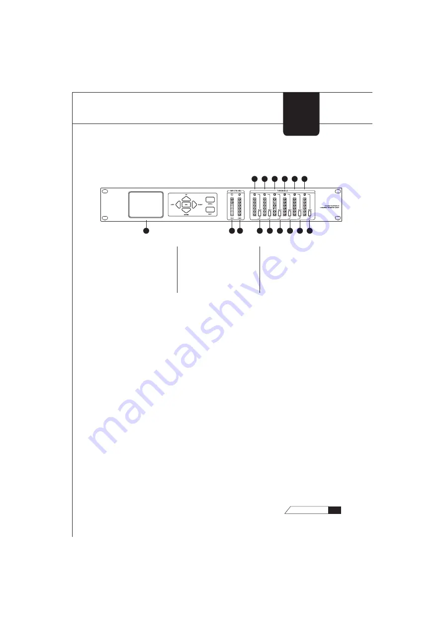
LCD Display

The true color LCD display of the 260™ provides the user with all of the 
vital processing information of the 260™ including: signal routing, 
configuration modes and effect unit editing. 

Function Buttons 

The function buttons of the 260™ allow direct access to all editing 
functions of the 260™. The buttons include <LEFT>, <RIGHT>, <UP>, 
<DOWN>, <MENU>, and < EXIT >. As to their functions, please refer to 
Chapter 2.

Input Meters 

The 260™ provides the user with two independent, six-segment input 
meters that range from -20~ +18 dBu. These meters monitor the signal 
level right after the input module.

GETTING 

STARTED

1.1Front Panel 

1. LCD Display
2. Input Meters 1
3. Input Meters 2
4. Output Mutes 1
5. Output Mutes 2

6. Output Mutes 3
7. Output Mutes 4
8. Output Mutes 5
9. Output Mutes 6
10. Output Meters 1

11. Output Meters 2
12. Output Meters 3
13. Output Meters 4
14. Output Meters 5
15. Output Meters 6

5

260 

USER


GUIDE

Summary of Contents for DESTINY EQ 260

Page 1: ...GECKO DESTINY EQ 260 OWNER S MANUAL OWNER S MANUAL www geckomusicgroup com www geckomusicgroup com...

Page 2: ...A grounding type plug has two blades and a third grounding prong The wide blade or the grounding prong is provided for your safety If the provided plug does not fit into your outlet consult an electr...

Page 3: ...of these permissible limits could result in some hearing loss To ensure against potentially dangerous exposure to high sound pressure levels it is recommended that all persons exposed to equipment ca...

Page 4: ...audiophile products you ever need Our engineering team is constantly doing R D to meet this goal I thank God that by His grace we have succeeded in developing the revolutionary C R I S T A L technolo...

Page 5: ...ON 41 WARRANTY 42 NOTES Congratulations on purchasing the GECKO DESTINY EQ 260 speaker management system We recommend that you take a moment and read through the manual as it provides information that...

Page 6: ...e editing performance is achieved in a simple and convenient way Apart from the 24 bit 48kHz codec the GECKO DESTINY EQ 260 also offers two independent channels of highly precise 28 bit DSP processing...

Page 7: ...tion of the 260 offers six electronically balanced XLR connectors Inputs 1 2 The input section of the 260 offers two electronically balanced XLR connectors Chapter 1 Getting Started 1 1Rear Panel Conn...

Page 8: ...260 allow direct access to all editing functions of the 260 The buttons include LEFT RIGHT UP DOWN MENU and EXIT As to their functions please refer to Chapter 2 Input Meters The 260 provides the user...

Page 9: ...the user with six independent six segment output meters that range from 20 18dBu GETTING STARTED 6 260 USER GUIDE Output Mutes The six output mute buttons are used for independently muting each output...

Page 10: ...rd when editing the character string to select the unit to be processed by going right on the main interface OK is used to enter the unit parameter editing mode on the main interface to exit or enter...

Page 11: ...made to delete the character strings when editing the text Mute1 is to mute output channel 1 to serve as the key of the number 1 when entering the password Mute2 is to mute output channel 2 to serve...

Page 12: ...background too When a dialog box is being operated the selected button will be highlighted 2 2 1 Program Menu Select a program number on the main interface by pressing Up Down There are 40 factory pr...

Page 13: ...program Save as Choose the item Save as and press the button OK Then a dialog box will appear as follows Use Up or Down to select the number of the program you intend to deal with If you want to renam...

Page 14: ...asting to a unit will overwrite all its parameters Do you want to continue Choose Yes to complete the pasting choose Cancel to cancel the operation This is illustrated as follows Combine is to combine...

Page 15: ...Divide on the popup menu to divide the unit into two and then set their parameters respectively 2 2 3 Input and Output Menu Select an input unit and press the button Menu A menu will appear as follow...

Page 16: ...NCTIONS 13 260 USER GUIDE Select an output channel and press the button Menu A menu will appear as follows Choose Move Up or Move Down to move the selected channel up or down so as to adjust the outpu...

Page 17: ...to help you set all security parameters Select a program number on the main interface and press Menu to enter the menu It will appear as follows 3 1 Program Locking No password is needed when locking...

Page 18: ...e saved and locked if you choose No the operation will be cancelled After the program is locked the item Lock Program on the menu turns into the item Unlock Program and the data of all the units in th...

Page 19: ...operation 3 2 Account Changing Since the security system has three levels high middle and low there can be three different levels of users accessing the unit The level of users goes like this Operator...

Page 20: ...account which will be highlighted in green accordingly Then press the button OK to complete the account changing or select Exit to cancel the operation password is composed of the Arabic numbers from...

Page 21: ...g box will appear to warn that The current program must be saved before locking the system Do you want to continue If you choose Yes the program will be saved and locked if you choose No the operation...

Page 22: ...he six Mute buttons can work as the keys of the numbers from 1 to 6 For example when you press Mute 1 you are entering the number 1 Should any error occur in the entering press Exit to cancel the ente...

Page 23: ...the longest being a six digit number The six Mute buttons can work as the keys of the numbers from 1 to 6 For example when you press Mute 1 you are entering the number 1 You have to enter the initial...

Page 24: ...s and explanations of all parameters within the 260 4 1 Pre Crossover EQ PE The 260 s Pre Crossover EQ section may be configured as a single or linkable 28 band graphic EQ or 9 Band PEQ GEQ GE The par...

Page 25: ...ider represents the gain of the frequency which ranges from 12 to 12 dB The buttons Up and Down can be used to adjust the gain of any center frequency of the 28 bands of the GEQ in 0 5 dB increments F...

Page 26: ...is turned off when Bypass is off the PEQ is turned on Band Center 20 1Hz to 20 7 kHz There are all together 9 bands of PEQ the frequency scopes of which are all from 20 1Hz to 20 7 kHz Band 1 is the L...

Page 27: ...pe which ranges from 3 to 12dB Octave when any band from Band 2 to Band 8 is selected the parameter stands for Q which ranges from 0 092 to 16 0 Level 12 dB to 12 dB To set the gain of the selected fr...

Page 28: ...e two parallel lines representing the MAX Attenuation are displayed in green when they are not selected Bypass When Bypass is on the box behind it is highlighted in green when the box is in white it m...

Page 29: ...n you want This ratio works opposite from that of the compressor or limiter If a ratio of 1 4 is selected a signal that is 1dB below the threshold will be reduced in gain so that it becomes 4dB below...

Page 30: ...ilter is turned on Notch To select the notch filter to set The frequency response curve of the selected one will be displayed in red Center 1 to 6 20 1Hz to 20 7KHz To select the desired notch filter...

Page 31: ...d by a fast limiter to prevent distortion by clipping The AGC Threshold meters show what region of the AGC the input signal is in The parameter setting interface is illustrated in the following diagra...

Page 32: ...the AGC output to be If the average level of the signal rises above the Target the gain will be reduced For signals with an average level below the Target the gain will be increased Window 1 dB to 10...

Page 33: ...t Bypass is off When Bypass is on the BP is turned off when Bypass is off the BP is turned on Channels 1 6 There are all together six channels The display of the channels depends on the setting of the...

Page 34: ...ype filter BW 6 12 18 24 for Butterworth type filter with slope of 6 12 18 or 24 dB Octave and LR12 24 36 48 for Linkwitz Riley type with slope of 12 or 24 dB Octave HF 20 1 Hz to 20 7KHz To adjust th...

Page 35: ...rface is as follows Bypass When Bypass is on the box behind it is highlighted in green when the box is in white it means that Bypass is off When Bypass is on the PEQ is turned off when Bypass is off t...

Page 36: ...een curve stands for the frequency response curve of the PEQ It can be illustrated in the following diagram Center Q 1 4 0 092 dB to 16 dB To set the Q or Bandwidth of the selected Parametric EQ Level...

Page 37: ...Limiter are as follows and are user adjustable COMPRESSOR CP The parameter setting interface is illustrated in the following diagram There are two points and two line segments on the interface The to...

Page 38: ...gnal has dropped below the threshold A longer hold time is useful in smoothing out the sound when compressing several fast peaks that are fairly close together in time In general some hold time helps...

Page 39: ...io R 1 0 1 to Inf 1 Ratio is the amount the unit reduces the signal level of the sound that is above the threshold A 2 1 ratio means that if the incoming signal is 2dB over the threshold the unit will...

Page 40: ...her frequency bands Hold 0 to 500 m Sec per band or global Hold is the time the limiter stays in gain reduction after the signal level has dropped below threshold Hold is useful when you want the limi...

Page 41: ...ntent is over the threshold For most signals the most natural compression is achieved when most of the signal content remains just below the threshold and only the peaks cross the threshold 4 8 Alignm...

Page 42: ...e in 0 02ft increments When the unit is based on meters coarse adjustments are made in 0 36m increments while fine adjustments are made in0 01m increments Length To set the amount of Speaker Alignment...

Page 43: ...tput and adjust phase compensation of loudspeakers The parameter setting interface is as follows Phase This parameter is used to set the phase to be positive or negative Use Up and Down to select or f...

Page 44: ...24 Bit Codec Dynamic Range 110dB Unweighted 112dB A Weighted Sample Rate 48kHz System Performance Type 28 Bit DSP 2 Dynamic Range 110 dB Unweighted 106dB Weighted THD N 0 002 Typical at 4dBu 1kHz 0dB...

Page 45: ...comply with the technical or safety regulations applicable in the country where the product is used 5 Damages defects caused by force of nature or any other condition that is beyond the control of GE...

Page 46: ...n the unit C O D with a separate invoice for freight and packing Such costs will also be invoiced separately when the buyer has sent in a written repair order Warranty Rights This warranty is exclusiv...

Reviews: