D
GB
F
E
I
Ru
3
09637-06.2015-DGbFEIRu
Contents
Page
3
Areas of application
8
3.1 Refrigerants
3.2 Oil charge
3.3 Limits of application
4
Compressor assembly
10
4.1 Storage and transport
4.2 Setting up
4.3 Pipe connections
4.4 Pipes
4.5 Laying suction and pressure lines
4.6 Operating the shut-off valves
4.7 Operating mode of the lockable service connections
5
Electrical connection
13
5.1 Information for contactor and motor contactor selection
5.2 Connection of the driving motor
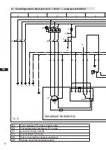
5.3 Circuit diagram for direct start 230 V
Δ
/ 400 V Y -->
with MP10
5.4 Electronic trigger unit MP10
5.5 Connection of the electronic trigger unit MP10
5.6 Functional test of the electronic trigger unit MP10
5.7 Circuit diagram for direct start 230 V
Δ
/ 400 V Y -->
with INT69 G
5.8 Electronic trigger unit INT69 G
5.9 Connection of the electronic trigger unit INT69 G
5.10 Functional test of the electronic trigger unit INT69 G
5.11 Start unloader
6 Commissioning
22
6.1 Preparations for start-up
6.2 Pressure strength test
6.3 Leak test
6.4 Evacuation
6.5 Refrigerant charge
6.6 Start-up
6.7 Avoiding slugging
6.8 Connection of oil level regulator
7 Maintenance
24
7.1 Preparation
7.2 Work to be carried out
7.3 Spare parts recommendation
7.4 Accessories
7.5 Extract from the lubricants table
7.6 Decommissioning
8
Technical data
26
9
Dimensions and connections
27
10 Declaration of conformity and installation
28
11 Service
29


