


Critical Power
Modifications reserved
Page 29/92
GE_UPS_USM_TLE_SUL_M62_1M0_2US_V010.docx
User Manual
TLE Series 625 - 750 - 1000 UL S2
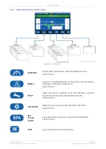
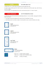
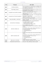
LEDs on Synoptic Diagram
LED 1 Rectifier
LED 2
Inverter
LED 3 Booster/Battery charger
LED 4 Automatic Bypass
LED 5 LOAD
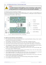
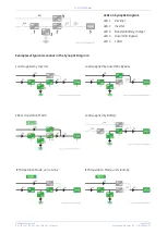
Examples of typical scenarios in the Synoptic Diagram:
Load supplied by Inverter
Load supplied by Automatic Bypass
eBoost Operation Mode
Load supplied by Battery
IEMi Operation Mode, unit on-line
IEMi Operation Mode, unit stand-by


