Module Setup
S768DAV – S7768DAV User Manual
Table 2. DATA SELECT SW1/SW2 Settings
Setting Data
Mode
Setting Data
Mode
0
Not Configured or Auto Configuration
8
RS485 two -wire, 2V offset
1
RS232
9
RS485 four-wire standard
2
RS232 with handshake
A
RS485 four-wire, 1V offset
3
TTL
B
RS485 four-wire, 2V offset
4
RS422 two-wire
C
Not used
5 Manchester/Biphase
D Not
used
6
RS485 two-wire Standard or SensorNet
E
Receiver Test mode
7
RS485 two -wire, 1V offset
F
Transmitter Test mode
2.3.2
A
UTO
D
ATA
C
ONFIGURATION
The S768DAV modules can be set for Auto Data Configuration, where the format of the data on channel
1 or channel 2 is controlled from one unit, either the transmitter or the receiver. To use the Auto Data
Configuration feature, perform the following.
1)
Set the DATA SELECT switches SW1 or SW2 on one unit to position 0 (default setting).
2)
Set the DATA SELECT switches SW1 or SW2 on the other unit to the desired format.
3)
If the data format needs to be changed for a particular channel, only the DATA SELECT switches
on one unit need to be changed. The other unit remains in position 0 and will auto-configure
according to the selected data format.
2.4
O
PTICAL
/V
IDEO
A
LARMS
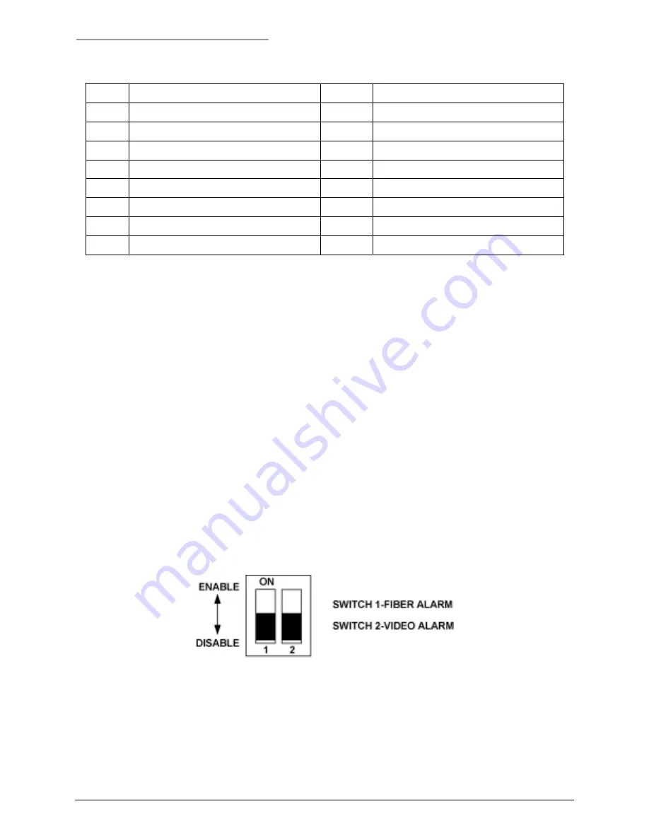
Rack cards are supplied with alarm functions that activate if the optical or video signal input to the module
fails. These alarms can be output to the rack power supply, where an audible alarm and alarm output
contact closure can be activated. The optical and video alarms are controlled using DIP switch SW3 on
the audio/data card. To set the optical and video alarms, see Figure 2 and Figure 4 and perform the
following.
Figure 4. ALARM Switch SW3
1)
Set switch SW3-1 to ON to enable the FIBER (optical) alarm.
2)
Set SW3-2 to ON to enable the VIDEO alarm.
10
11-0768DAV-B/ December 2003


